Injection system driven by piezoelectric sheet

A technology of injection system and piezoelectric sheet, applied in the field of medical devices, can solve the problems of aggravating the burden on the heart, blood backflow, no therapeutic effect, etc., and achieves the effect of being convenient to move and carry, and increasing the gas pressure.

Active Publication Date: 2019-06-14
ZHEJIANG NORMAL UNIVERSITY
View PDF6 Cites 0 Cited by
  • Summary
  • Abstract
  • Description
  • Claims
  • Application Information

AI Technical Summary

Problems solved by technology

This infusion mode will bring many problems in actual use: the flow rate is adjusted manually, and the flow control accuracy is not enough; the infusion bottle needs to be held high by others when the patient walks or goes to the toilet, which is inconvenient to move and the height of the infusion bottle is not high enough. Make the blood flow back; patients or nurses need to be guarded for a long time, if the infusion is not found in time, it may cause accidents; the liquid medicine is in contact with the air, and the ambient air may be polluted when the air is unclean
In addition to the above direct problems, sometimes the infusion time is shortened by reducing the amount of solution, speeding up the infusion speed, etc., which not only increases the burden on the heart, but also affects the therapeutic effect: intramuscular injection and subcutaneous injection in a relatively short period of time. The biggest disadvantage of injecting into muscle or subcutaneous is that the blood drug concentration varies greatly within an injection cycle, which is not conducive to the effective absorption and utilization of drugs, because most drugs have a better concentration range in the human body, and when the drug concentration is too high Has toxic side effects, if it is too low, it will have no therapeutic effect

Method used


Image

  • Injection system driven by piezoelectric sheet
  • Injection system driven by piezoelectric sheet
  • Injection system driven by piezoelectric sheet

Examples


Embodiment Construction

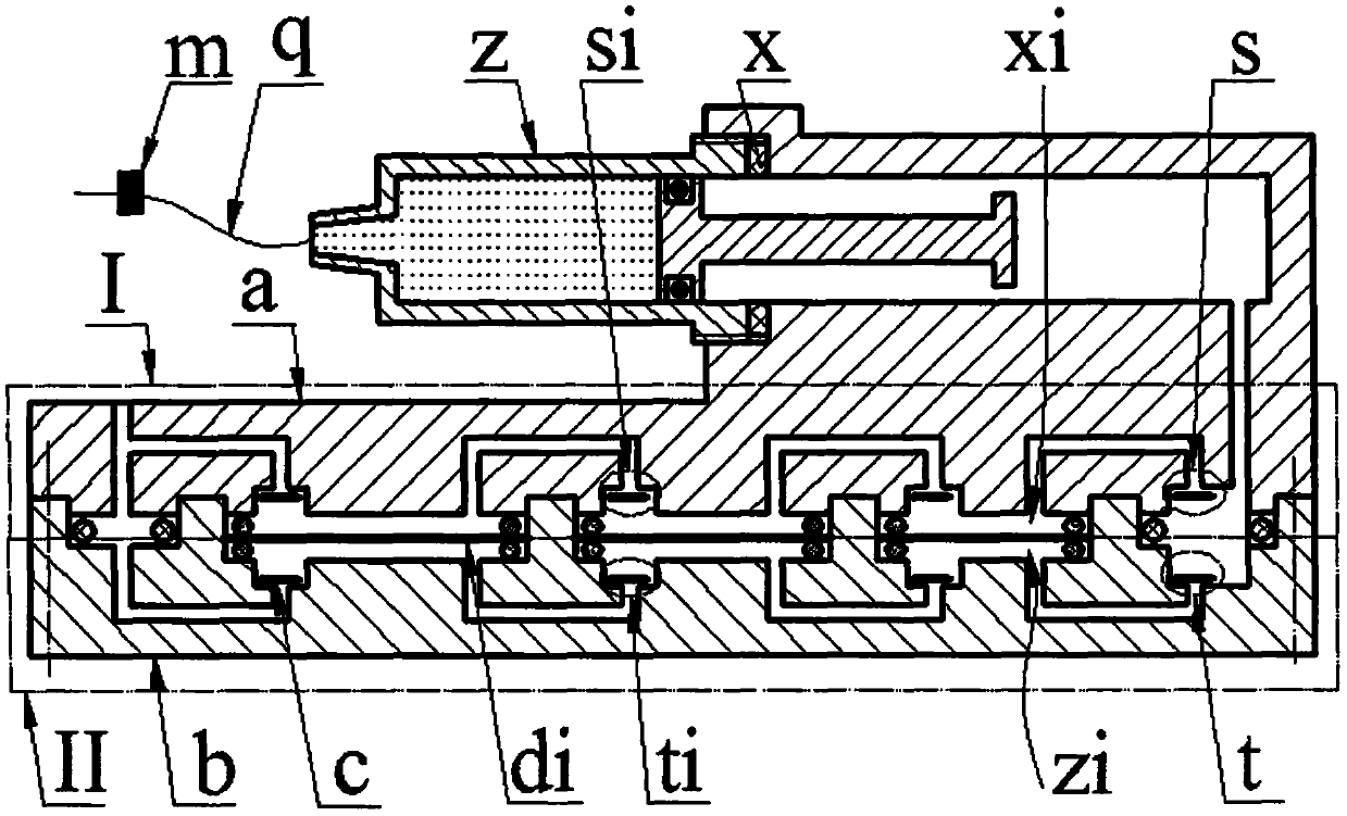
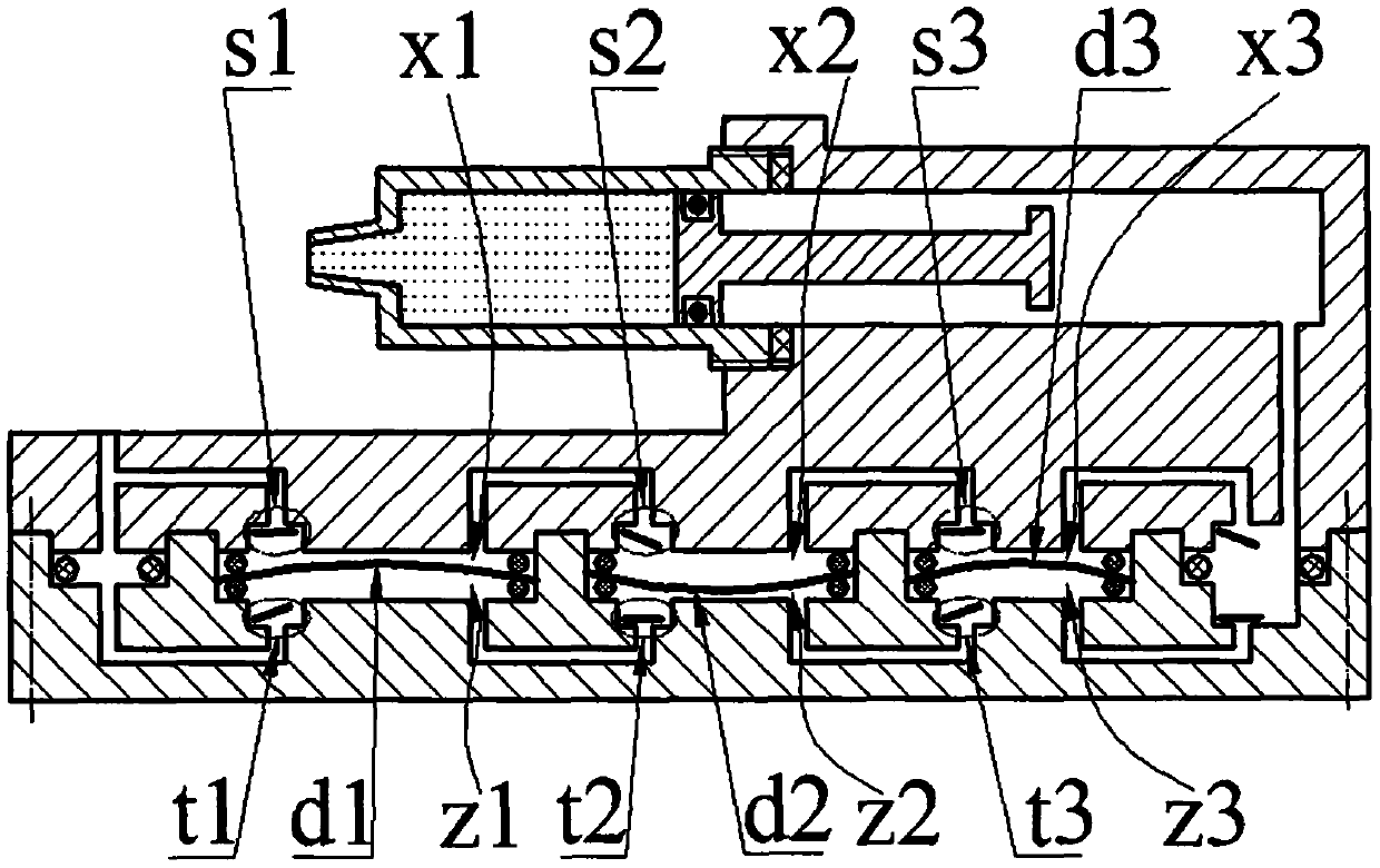
[0015] The main body a is installed on the base b through screws, and the cartridge z1 of the syringe z is installed on the end of the cylinder cavity a9 on the top of the main body a through threads. The piston z2 is placed in the cartridge z1 and forms a medicine chamber z3 with the cartridge z1. There is a sealing gasket x between z1 and the cylinder chamber a9; the push rod of the piston z2 is placed in the cylinder chamber a9, and the infusion tube q with the flow valve m and the needle is installed on the cartridge z1; the bottom of the main body a is provided with a left convex The platform a1, the right boss a2 and at least two body platforms a3i with different diameters, the diameters of the body platforms a3i decrease from left to right, the left boss a1 is provided with an upper entrance hole a4, and the right boss a2 There is an upper outlet a5 communicating with the cylinder cavity a9 through the upper outlet a8, and an upper inlet a6 and an upper air outlet a7 are...


PUM


Abstract

The invention relates to an injection system driven by a piezoelectric sheet and belongs to the field of medical instruments. A main body is arranged on a base, and an injector is arranged at the endpart of a cylinder cavity of the main body; the bottom of the main body is provided with a left boss, a right boss and at least two body tables with unequal diameters, the left boss is provided with an upper inlet hole, the right boss is provided with an upper outlet cavity communicated with the cylinder cavity through the upper outlet hole, and the body tables are provided with an upper inlet cavity and an upper outlet hole; the top of the base is provided with a left cavity, a right cavity and a body cavity which are respectively equal to the number and the diameter of the body table, the left cavity is provided with a lower inlet hole, the right cavity is provided with a lower outlet cavity, and the body cavity is provided with a lower inlet cavity and a lower outlet hole; the upper andlower inlet and outlet cavities and the valve plates installed in the upper and lower inlet and outlet cavities respectively form upper and lower inlet and outlet valves; the left boss is arranged inthe left cavity, the right boss is arranged in the right cavity, the body platform presses the piezoelectric driver into the body cavity through a sealing ring to form an upper compression cavity anda lower compression cavity, the upper compression cavity is connected in series to form an upper compression unit, the lower compression cavity is connected in series to form a lower compression unit, and the upper compression unit and the lower compression unit are connected in parallel; in operation, the deformation directions of the left and right adjacent drivers are opposite.

Description

technical field [0001] The invention belongs to the field of medical equipment, and in particular relates to an injection system driven by a piezoelectric sheet. Background technique [0002] Existing injections mainly include intravenous injection, intramuscular injection and subcutaneous injection. Intravenous injection is also called infusion drug administration. Most of the existing infusion devices are composed of infusion bottles, infusion tubes and infusion stands. This infusion mode will bring many problems in actual use: the flow rate is adjusted manually, and the flow control accuracy is not enough; the infusion bottle needs to be held high by others when the patient walks or goes to the toilet, which is inconvenient to move and the height of the infusion bottle is not high enough. Make the blood flow back; the patient or the nursing staff need to watch for a long time, if the infusion is not found in time, it may cause an accident; the liquid medicine is in conta...

Claims


Application Information

Patent Timeline
Patent Type & Authority Applications(China)
IPC IPC(8): A61M5/155A61M5/168
Inventor 张忠华林仕杰陈泽锋王淑云马继杰杨泽盟
Owner ZHEJIANG NORMAL UNIVERSITY
Why Eureka
Try Eureka