Integrating device capable of controlling wall thickness of bottle blowing machine with crank connecting rod mechanism driven by motor
A crank-link mechanism and motor-driven technology is applied in the field of plastic extrusion blowing wall thickness control devices, which can solve the problems of long-term use by users that affect the wall thickness control effect, shortened operating life of the screw mechanism, and short extrusion and blowing control movement strokes. Achieve easy installation and maintenance, avoid hydraulic pollution, stable and reliable structure
- Summary
- Abstract
- Description
- Claims
- Application Information
AI Technical Summary
Problems solved by technology
Method used
Image
Examples
Embodiment 1
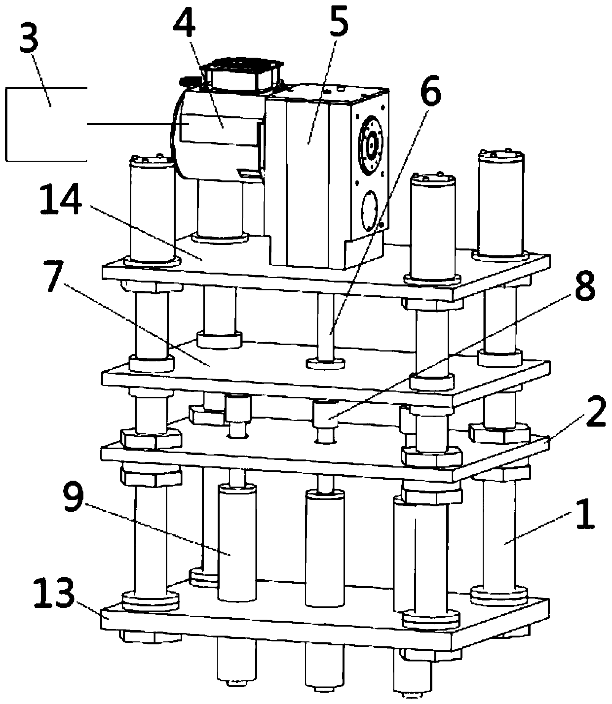
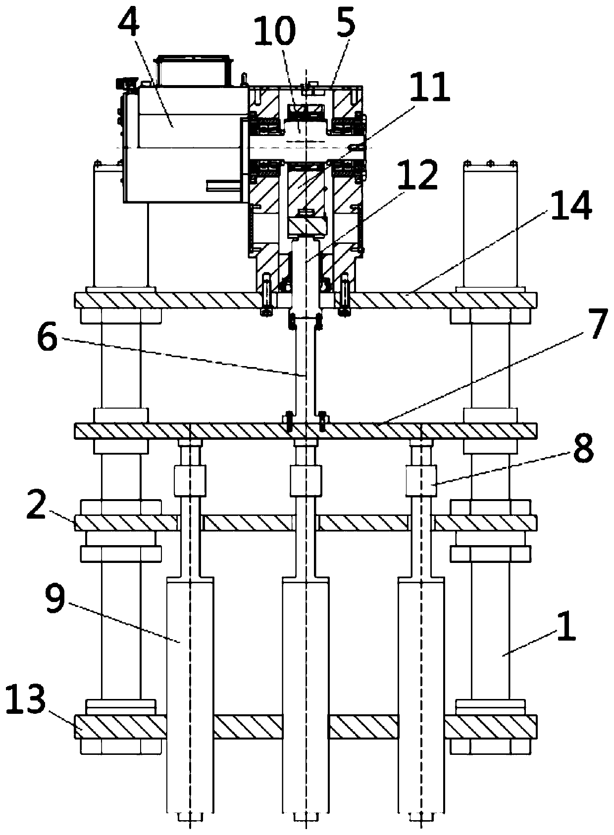
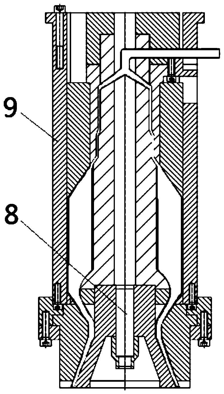
[0032] see Figure 1-3 , in an embodiment of the present invention, an integrated device for controlling the wall thickness of a blow molding machine by a motor-driven crank-link mechanism, including a frame, a servo motor 4 and a crank-link mechanical device are installed on the top of the frame, and the servo The motor 4 is connected with the mandrel moving platen 7 through a crank connecting rod mechanical device and drives the mandrel moving platen 7 to move up and down; the bottom of the frame is fixed with a plurality of extrusion dies 9 for extrusion blowing moulds, The extrusion die head 9 is equipped with an extrusion die mandrel 8, the upper end of the extrusion die mandrel 8 is connected and fixed with the mandrel movable platen 7, and the movement of the mandrel is controlled by the servo motor 4 and the crank connecting rod mechanical device. The position of the template 7 is further controlled to control the position of the extrusion die mandrel 8 relative to the...
Embodiment 2
[0036] see figure 1 and 2 , the difference between this embodiment and embodiment 1 is:
[0037] In this embodiment, the crank-link mechanical device includes a crank-link mechanism box 5, which is installed and fixed on the upper mounting plate 14 of the frame, and the inner upper part of the crank-link mechanism box 5 A crank eccentric shaft 10 is provided, and one or two servo motors 4 can be provided. When the servo motor 4 is one, the servo motor 4 is installed and fixed on the outside of the crank linkage casing 5, and the crank eccentric shaft 10 The side end of the motor extends out and serves as the rotor shaft of the servo motor 4 at the same time, or the output shaft of the servo motor 4 is connected with the crank eccentric shaft 10 through a coupling; when there are two servo motors 4, the two servo motors 4 are installed and fixed respectively On both sides of the outside of the crank-link mechanism casing 5, and the two ends of the crank eccentric shaft 10 res...
Embodiment 3
[0042] see figure 1 , the difference between this embodiment and embodiments 1 and 2 is:
[0043] In this embodiment, it also includes a digital crank connecting rod cam curve conversion software system and a servo drive controller 3 for controlling the servo motor 4, the servo drive controller 3 is electrically connected with the servo motor 4, and the digital crank connecting rod cam The curve conversion software system includes human-computer interaction interface and digital conversion crank connecting rod curve software. Through the digital crank connecting rod cam curve conversion software system, the digital control cam curve of the wall thickness of the product is converted into the motion angle cam curve of the crank connecting rod mechanical device. The calculation data is transmitted to the servo drive controller 3 through the digital interface (industrial Ethernet), and the servo drive controller 3 controls the movement of the servo motor 4 .
[0044] Method to re...
PUM
 Abstract
Description
Claims
Application Information
 - R&D
- Intellectual Property
- Life Sciences
- Materials
- Tech Scout
- Unparalleled Data Quality
- Higher Quality Content
- 60% Fewer Hallucinations
Browse by: Latest US Patents, China's latest patents, Technical Efficacy Thesaurus, Application Domain, Technology Topic, Popular Technical Reports.
© 2025 PatSnap. All rights reserved.Legal|Privacy policy|Modern Slavery Act Transparency Statement|Sitemap|About US| Contact US: help@patsnap.com


