Improved porous wire type binding machine

A binding machine and wire-type technology, applied in the direction of binding, etc., can solve the problems of increased contact resistance of conductive rubber pads, damage to drills, conductive rubber pads, and excessive downward movement of drills, so as to reduce the probability of electrical failures and avoid manual operations. Effect of compression and manual decompression, avoiding decoupling

Pending Publication Date: 2019-06-14
周添星
View PDF6 Cites 3 Cited by
  • Summary
  • Abstract
  • Description
  • Claims
  • Application Information

AI Technical Summary

Problems solved by technology

This type of binding machine has the disadvantage of poor stability. In a hot and humid environment, the contact resistance of the conductive rubber pad increases rapidly with time, and the drill cannot trigger the conductive rubber pad within the safe stroke, resulting in excessive downward movement of the drill. Damage caused by drill bits, conductive pads and machine needles

Method used


Image

  • Improved porous wire type binding machine
  • Improved porous wire type binding machine
  • Improved porous wire type binding machine

Examples


Embodiment 1

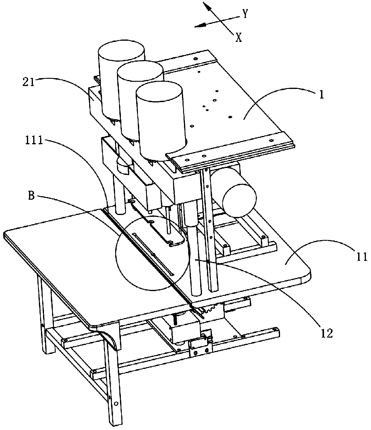
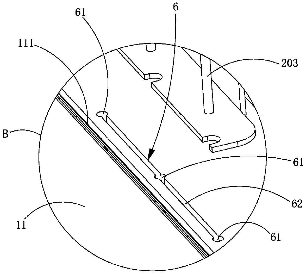
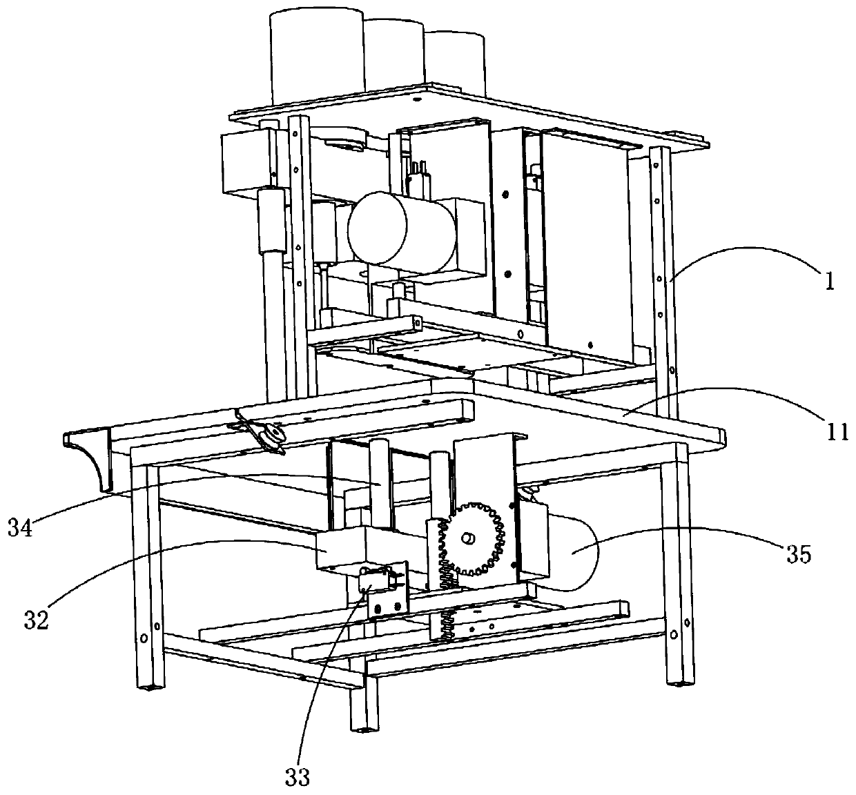
[0043] An improved perforated wire binding machine, such as Figure 1 to Figure 5 As shown, the multi-hole wire binding machine includes a frame 1, a control circuit, a binding platform 11, a drilling mechanism 2 and a wire feeding mechanism, and the binding platform 11 is arranged at the middle part of the frame 1; Above, the drilling mechanism 2 has at least two drills 203; the wire feeding mechanism is positioned above or below the binding platform 11, and the wire feeding mechanism has the same machine needles 31 as the number of drills, and each machine needle 31 is connected to the corresponding drill respectively. 203 is longitudinally aligned or vertically aligned, and it is characterized in that: the binding platform 11 is provided with an avoidance notch 6, the avoidance notch 6 runs through the binding platform 11 up and down, the avoidance notch 6 is arranged below the drill 203, and each drill 203 vertically Straight alignment avoids notch 6; Binding platform 11 o...

Embodiment 2

[0080] The composition structure of the porous thread binding machine provided in this embodiment is basically the same as that of the porous thread binding machine provided in the above-mentioned embodiment 1, the difference is that, as Figure 14 As shown, a plurality of protrusions are symmetrically formed on the front and rear sides of the avoidance notch 6, and the protrusions are set in the shape of protruding teeth, and each protrusion is respectively surrounded by the edge of the avoidance notch 6 to form three drill matching holes. 61, each drill matching hole 61 is vertically aligned with the corresponding drill 203 respectively, each drill matching hole 61 is not provided with a threading groove 62 at a lateral interval, and a threading gap is formed between two adjacent protrusions before and after, so as to It is realized that the binding line passes through the binding platform 11 completely. The binding method of the perforated wire binding machine is the same a...


PUM


Abstract

The invention discloses an improved porous wire type binding machine. The improved porous wire type binding machine comprises a machine frame, a control circuit, a binding platform, a drilling mechanism and a wire feeding mechanism, wherein the binding platform is arranged in the middle of the machine frame; the drilling mechanism is arranged above the binding platform, and the drilling mechanismis provided with three drilling cutters; the wire feeding mechanism is positioned below the binding platform, the wire feeding mechanism is provided with three machine needles, each machine needle isaligned with the corresponding drilling cutter in parallel, a receding groove opening is formed in the binding platform, the binding platform is used for receding the drilling cutters and the machineneedles, the receding groove opening penetrates through the binding platform up and down, the receding groove opening transversely penetrates each drilling cutter and each machine needle, and the width of the receding groove opening is larger than the outer diameter of the drilling cutters and the outer diameter of the machine needles. Compared with the prior art, the binding machine can be used for receding the use of a conductive rubber pad and a rubber pad translation mechanism, receding the drill cutters in the downward drilling process, so that a binding line can be conveyed to penetratethrough the binding platform and a binding hole, and the whole machine is low in cost and good in stability.

Description

technical field [0001] The invention relates to the technical field of financial binding machines, in particular to an improved perforated wire binding machine. Background technique [0002] Most enterprises or government agencies require the use of threading for their documents and financial documents. At present, the most commonly used wire binding machine is a manual wire binding machine. The manual wire binding machine includes a manual drilling mechanism and During the use of the drilling platform, it is necessary to manually drive the manual drilling mechanism to perform drilling operations on the documents to be bound, and then pass the binding line through the drilling holes by hand, and finally perform manual knotting to bind the documents or financial documents into a book. This type of manual thread binding machine has problems such as difficulty in use and difficulty in operation. [0003] In the prior art, there is a wire binding machine that can realize autom...

Claims


Application Information

Patent Timeline
Patent Type & Authority Applications(China)
IPC IPC(8): B42B2/04
Inventor 周添星
Owner 周添星
Why Eureka
Try Eureka