Hydraulic braking system of low-floor tramcar

A technology of hydraulic brakes and trams, applied in the direction of brakes, brake transmission devices, vehicle components, etc., can solve the problems of inconvenient operation, long time consumption, inconvenient observation, etc., achieve flexible modular design, convenient The effect of modular design

Active Publication Date: 2019-06-14
嘉兴市钧萍轨道交通科技有限公司
View PDF5 Cites 8 Cited by
  • Summary
  • Abstract
  • Description
  • Claims
  • Application Information

AI Technical Summary

Problems solved by technology

[0006] (1) For the existing hydraulic station, it is usually difficult to provide a variety of pressures to control the hydraulic brake caliper for multifunctional operations such as relief and braking operations
[0007] (2) For the existing auxiliary relief device, when the hydraulic unit fails, one of the above two methods must be used for manual relief operation. It takes a long time to relieve the operation, so that the rail transit vehicle cannot be evacuated quickly when the hydraulic unit fails
The push rod in the part must have a mechanism to prevent rotation during normal use; however, the existing structure manual release

Method used


Image

  • Hydraulic braking system of low-floor tramcar
  • Hydraulic braking system of low-floor tramcar
  • Hydraulic braking system of low-floor tramcar

Examples


Embodiment 1

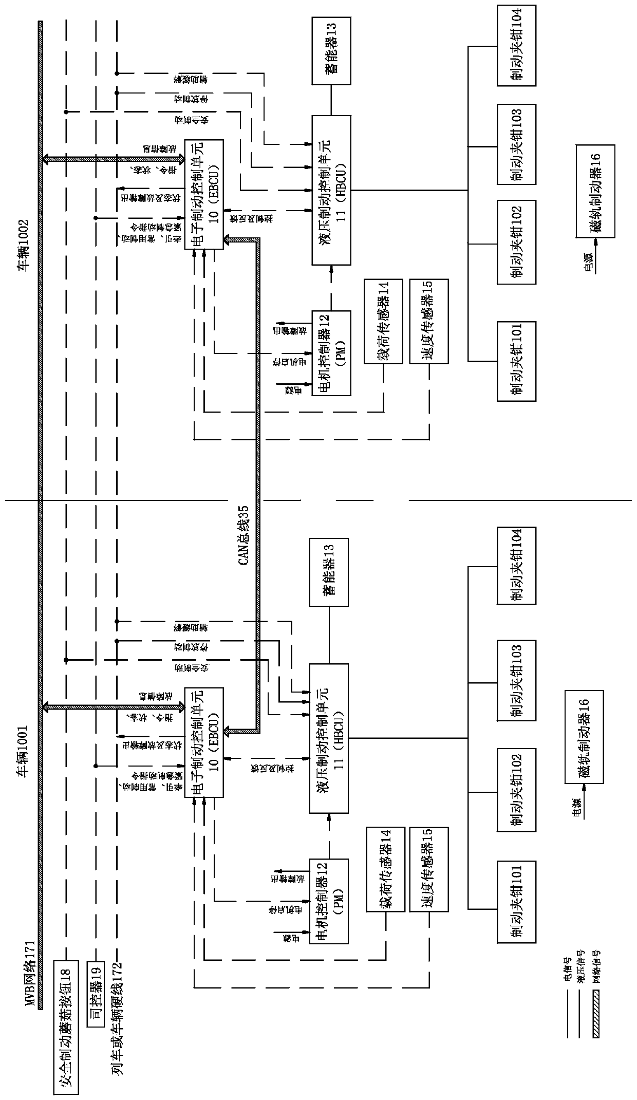
[0046] see figure 1 and figure 2 , The hydraulic brake system 1 of the present invention includes a hydraulic brake control system, a foundation brake device and a magnetic track brake 16 . During the working process, the hydraulic braking system exchanges information with the braking command generation system through the communication system. In this embodiment, two vehicles, vehicle 1001 and vehicle 1002, are used as an example to illustrate it. Of course, according to actual needs, multiple vehicles can be grouped for braking control. The bogie is equipped with a hydraulic brake caliper 101 , a hydraulic brake caliper 102 , a hydraulic brake caliper 103 and a hydraulic brake caliper 104 . Since the structures of the braking systems on the two vehicles are the same, in the following description, only the braking system on the vehicle 1001 is taken as an example for illustration. The hydraulic brake caliper can be either a shaft-disc brake or a wheel-disc brake.

[0047]...

Embodiment 2

[0066] As the description of Embodiment 2 of the present invention, only the differences from Embodiment 1 above will be described below, that is, the structure of the hydraulic station in the hydraulic control unit will be mainly described.

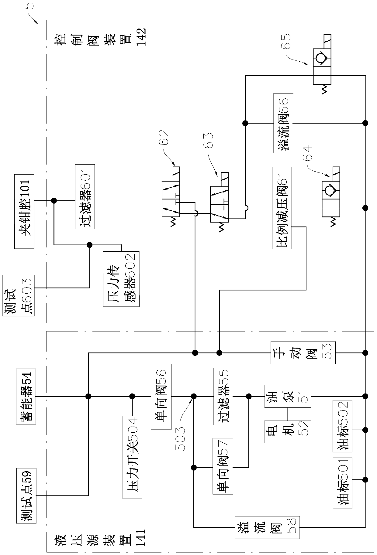
[0067] see Figure 3 to Figure 7 , the hydraulic station 5 includes an installation housing 7, a hydraulic source device 141 and a control valve device 142; wherein, the valve device 142 is used to carry out the process of supplying hydraulic oil from the hydraulic source device 141 to the clamp chamber 10 of the hydraulic brake caliper control.

[0068] Such as Figure 3 to Figure 7 As shown, the hydraulic source device 141 includes an oil tank, an oil pump 51 , an oil pump driving motor 52 , a manual valve 53 , an accumulator 54 , a filter 55 , a check valve 56 , a check valve 57 and a relief valve 58 . Along the traveling direction of the hydraulic oil in the oil circuit, the oil pump 51, the filter 55 and the one-way valve 56 are s...

Embodiment 3

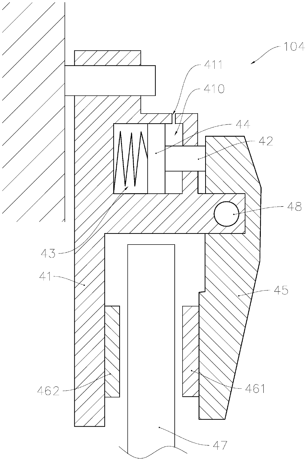
[0087] As the description of Embodiment 3 of the present invention, only the differences from Embodiment 1 or Embodiment 2 will be described below, that is, the structure of the suspension device in the magnetic rail brake will be mainly described.

[0088] see Figure 8 to Figure 10 The magnetic track brake 3 of the present invention includes a suspension bracket 310, a suspension device 311 and a brake electromagnet (not shown in the figure), the brake electromagnet is suspended on the suspension bracket 310, and the two ends of the suspension bracket 310 are connected by the suspension device 311 Suspended on the bogie mounting bracket 301, so that the brake electromagnet is arranged between the two wheels on the same side and suspended above the rail.

[0089] Such as Figure 8 to Figure 10 As shown, the suspension device 311 includes a suspension sleeve 32 , a limit sleeve 33 , a boom 34 , a return spring 312 , a lock nut 35 , a dust cover 36 , a joint seat 315 and a joi...


PUM


Abstract

The invention relates to a hydraulic braking system of a low-floor tramcar and belongs to the technical field of rail vehicles. The hydraulic braking system comprises a hydraulic brake control system,a basic brake device and a magnetic rail brake; the hydraulic brake control system comprises a speed sensor, a load sensor and brake control devices, wherein the speed sensor, the load sensor and thebrake control device are arranged on each bogie; each brake control device can independently control the braking force of the bogie and comprises an electronic brake control unit and a hydraulic brake control unit; and a communication system arranged between a command generation system and the hydraulic brake control system includes a first communication line for information interaction between the brake command generation system and a plurality of brake control devices, and a second communication line for information interaction between two adjacent electronic brake control units. Based on the improvement of the braking system structure, the braking system can be flexibly configured according to vehicles in different groups to facilitate modular design, and can be widely applied to the fields of manufacturing such as rail vehicles.

Description

technical field [0001] The invention relates to a braking system for a rail transit vehicle, in particular to a hydraulic braking system for a low-floor tram. Background technique [0002] Low-floor trams do not need to build platforms on the side of the track because the distance between the bottom plate and the rail surface is usually less than 40 cm, and the turning radius is small, so the line track can be directly laid on the existing roads in the city. [0003] Since line tracks can be laid directly on urban roads, the operating environment of low-floor trams is different from that of subways. They can operate in commercial areas without independent right of way, making their operating intervals intersect with pedestrians and vehicles. In the event of an emergency, the priority is to stop the vehicle to avoid hazards to pedestrians, so the deceleration requirements for low-floor trams are high. [0004] Due to the low floor surface of the low-floor tram, the space und...

Claims


Application Information

Patent Timeline
IPC IPC(8): B60T13/66B60T13/68
Inventor 莫亦荣仲云龙邬培生孙荣
Owner 嘉兴市钧萍轨道交通科技有限公司
Why Eureka
Try Eureka