
Intelligent automatic cable conveyor

An automatic conveying and intelligent cable technology, which is applied in transportation and packaging, conveying filamentous materials, and thin material processing, etc., can solve the problems of inaccurate grasp of real-time changes in pressing force, high labor intensity, and waste of electric energy, etc., to achieve Reduce efficiency and labor intensity, prevent water invasion, and monitor the real effect of data

Pending Publication Date: 2019-06-14
CHANGLAN CABLE ACCESSORIES
View PDF0 Cites 5 Cited by
  • Summary
  • Abstract
  • Description
  • Claims
  • Application Information

AI Technical Summary

Problems solved by technology

At present, there are the following deficiencies in the laying process of large and long cables: 1. The control method adopted by the equipment at present is either to start at the same time or to arrange personnel to control the equipment on site. Because the cable has not reached the equipment at the same time, the equipment is idling at this time. , needs to waste a certain amount of electric energy; 2. Arrange personnel to start on site, and the cost of personnel input is relatively high; 3. At present, most conveyors use crawler type, and the opening and closing of the crawler adopts a hand-cranked double-headed screw rod to open and close the crawler until the cable is clamped. , this part requires personnel to adjust the screw rod, which is labor-intensive; 4. When manually clamping the cable, the torque wrench is currently used to judge the clamping torque on the cable, and the clamping force on the cable cannot be accurately Intuitively know; in the actual cable laying, how much is the pressing force of the conveyor on the cable, and the real-time changes of the pressing force cannot be accurately grasped, so the quality of the cable laying cannot be monitored in real time, and this method cannot be accurate and real-time Guide the actual size of the pressing force and whether it will cause damage to the cable

Method used


Image

  • Intelligent automatic cable conveyor
  • Intelligent automatic cable conveyor
  • Intelligent automatic cable conveyor

Examples


Embodiment Construction

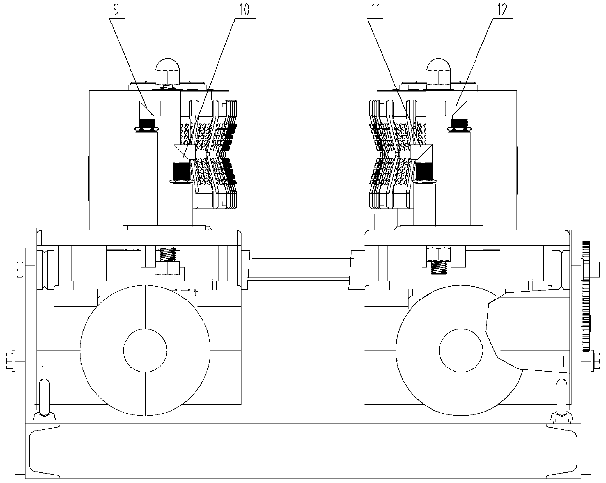
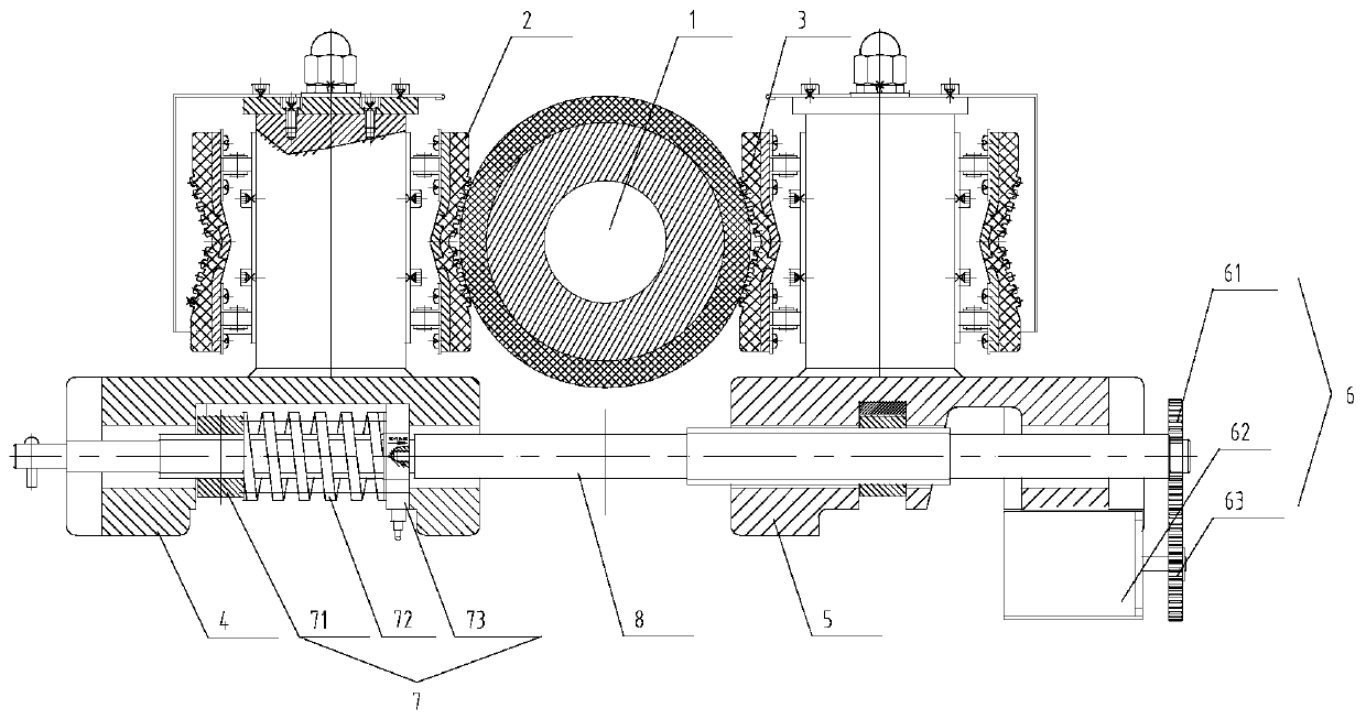
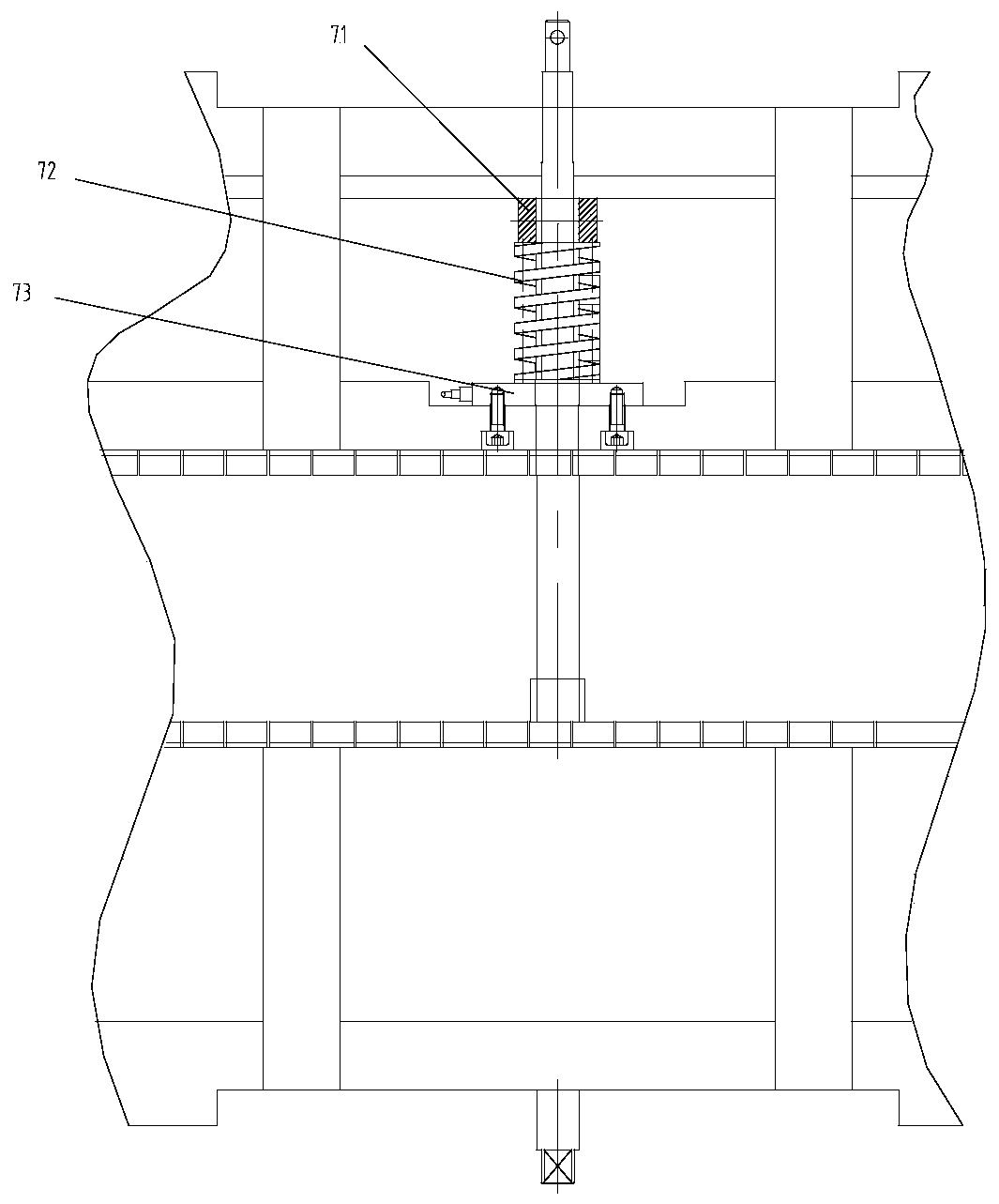
[0028] In order to better understand the present invention, the invention will be described in further detail below with reference to the accompanying drawings and implementation examples, but the embodiments of the present invention are not limited to this, and the protection scope of the present invention also relates to the ability of those skilled in the art according to the concept of the present invention. The equivalent technical means that come to mind.

[0029] like Figure 1-3 As shown, an intelligent cable automatic conveyor includes a left bracket 5, a right bracket 4 slidably installed on the conveyor base, and a first conveyor track 2 and a second conveyor track respectively installed on the opposite surfaces of the left and right brackets 4 3. The first conveying crawler 2 and the second conveying crawler 3 are driven by the conveying motor 13 to be conveyed in the same direction, so that a cable 1 conveying channel is formed between the first conveying crawler ...


PUM


Abstract

The invention relates to an intelligent automatic cable conveyor. A position sensor group for detecting a position of a cable is arranged at the inlet of a cable conveying channel, so that a caterpillar band is driven automatically to move through a conveying motor when the position sensor group senses the cable. A left bracket and a right bracket are driven by a lead screw electric driving mechanism to move synchronously oppositely or reversely, so as to clamp the cable placed in the cable conveying channel automatically. A pressing force detecting device for detecting a pressing force of thecable is arranged in the right bracket. The intelligent automatic cable conveyor can achieve automatic clamping of the cable, adjustable speed and automatic conveying and form closed-loop control, sothat the pressing force of the cable is adjusted automatically according to a set threshold value. Meanwhile, the conveyor can be adjusted in speed according to the field construction situation, so that the labor intensity and the cost of constructors are reduced greatly, and the intelligent automatic cable conveyor has the advantages of high cable paving quality and high efficiency.

Description

technical field [0001] The invention relates to an intelligent cable automatic conveyor. Background technique [0002] In the traditional ultra-high voltage long-distance, large-section power cable laying construction method, the cable is mainly transported by means of tractor + conveyor, etc. Due to the long cable length, long cable transport distance, and large number of conveyor arrangements, currently Mostly, at least one person is arranged in each equipment to operate the cable conveyor, and the start / stop of the main laying equipment and the manual screw rod realize the clamping of the cable. At present, there are the following shortcomings in the laying process of large and long cables: 1. The current control method of the equipment is either to start at the same time or arrange personnel to control the equipment on site. At the same time, since the cable has not yet reached the equipment, the equipment is idling at this time. , need to waste a certain amount of elec...

Claims


Application Information

Patent Timeline
IPC IPC(8): B65H51/18
Inventor 李绍斌刘勇叶波左格
Owner CHANGLAN CABLE ACCESSORIES
Learn More