Pulse detonation engine

A pulse detonation, engine technology, applied in engine components, mechanical equipment, air inlets of turbine/propulsion devices, etc., can solve the problems of acceleration energy loss, unfavorable thrust-to-weight ratio, reduced engine reliability and service life, etc. The effect of reducing back-propagation loss, small intake resistance, and short intake time

Active Publication Date: 2019-06-14
AECC HUNAN AVIATION POWERPLANT RES INST
View PDF6 Cites 0 Cited by
  • Summary
  • Abstract
  • Description
  • Claims
  • Application Information

AI Technical Summary

Problems solved by technology

Existing pulse detonation engines mostly adopt the intake valve structure to meet the requirements of unsteady detonation combustion for indirect intake. The intermittent intake mode of pulse detonation engines currently mostly adopts the intake valve structure, but it increases the The complexity of the structure and the difficulty of coordinated control of the vibration engine also reduce the reliability and service life of the entire engine. At the same time, the gas frequently stops flow and accelerates causing energy loss.
[0004] In addition, there are also some pulse detonation engines with a fixed intake head structure, and the pulse detonation engine with a fixed intake head, because the pressure of the detonation chamber is much higher than that of the intake port during the detonation stage, the open fixed There is a large back-propagation loss in the intake channel, and at the same time, the cone-shaped solid intake head also increases the mass of the pulse detonation engine, which is not conducive to improving the thrust-to-weight ratio

Method used


Image

  • Pulse detonation engine
  • Pulse detonation engine

Examples


Embodiment Construction

[0031] Example embodiments will now be described more fully with reference to the accompanying drawings. Example embodiments may, however, be embodied in many forms and should not be construed as limited to the embodiments set forth herein; rather, these embodiments are provided so that this disclosure will be thorough and complete, and will fully convey the concept of example embodiments to those skilled in the art. The same reference numerals in the drawings denote the same or similar structures, and thus their detailed descriptions will be omitted.

[0032] Although relative terms such as "upper" and "lower" are used in this specification to describe the relative relationship of one component of an icon to another component, these terms are used in this specification only for convenience, for example, according to the description in the accompanying drawings directions for the example described above. It will be appreciated that if the illustrated device is turned over so...


PUM


Abstract

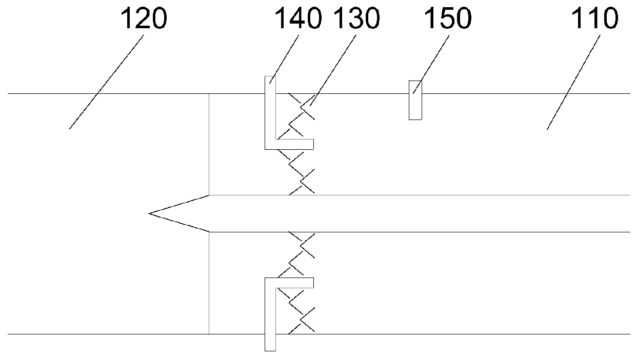
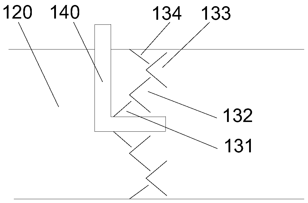
The invention relates to a pulse detonation engine. The detonation engine comprises a detonation tube and an air inlet part; the air inlet part comprises conical flow guide caps, at least one annularV-shaped groove flow guide plate, annular flow guide plates and a support; the flow guide caps and the annular V-shaped groove flow guide plates are arranged on the support; the support and the annular flow guide plates are fixedly connected with the detonation tube; the openings of the conical flow guide caps and the openings of the annular V-shaped groove flow guide plates face the outlet of thedetonation tube; the annular flow guide plate is inclined towards the side of the outlet of the detonation tube; the conical flow guide caps and the annular V-shaped groove flow guide plates are sequentially distributed in the axial direction of the detonation tube towards the outlet and are sequentially distributed from inside to outside in the radial direction of the detonation tube; the conical flow guide caps, the annular V-shaped groove flow guide plates and the annular flow guide plates are arranged at intervals, and the orthographic projections of every two adjacent ones on a plane inthe axial direction of the detonation tube have an overlapped area; and the orthographic projections of every two adjacent ones on a plane in the radial direction of the detonation tube have an overlapped area.

Description

technical field [0001] The present disclosure relates to the technical field of engines, in particular, to a pulse detonation engine. Background technique [0002] The pulse detonation engine is a new concept propulsion system based on detonation combustion. The detonation wave generated by detonation combustion is directly used in the combustion chamber to compress the gas and generate power. Compared with the traditional engine, the pulse detonation engine saves the compressor, turbine and other components, and has the advantages of simple structure, high thrust-to-weight ratio, wide operating range, and low use and maintenance costs. It is one of the ideal power for future advanced aerospace vehicles. one. [0003] The intake structure of the air-breathing pulse detonation engine has an important influence on the working characteristics of the engine. Existing pulse detonation engines mostly adopt the intake valve structure to meet the requirements of unsteady detonatio...

Claims


Application Information

Patent Timeline
IPC IPC(8): F02K7/02F02C7/04
Inventor 张坤王亮许炼谭云杰
Owner AECC HUNAN AVIATION POWERPLANT RES INST
Why Eureka
Try Eureka