Resistance-type strain sensor and strain measurement method

A technology of resistive strain and strain sensors, applied in the direction of electric/magnetic solid deformation measurement, electromagnetic measurement devices, etc., can solve the problems of unsuitable long-term precision measurement, permanent damage or creep of microstructure, etc.

Active Publication Date: 2019-06-14
INST OF MECHANICS - CHINESE ACAD OF SCI
View PDF26 Cites 8 Cited by
  • Summary
  • Abstract
  • Description
  • Claims
  • Application Information

AI Technical Summary

Problems solved by technology

Although these studies have made great progress in the design scheme, almost all strain sensors will experience permanent damage or creep of the microstructure within the range, and their high stretchability is based on silicone-like elastomers, so they are not suitable for Long-term precision measurement

Method used


Image

  • Resistance-type strain sensor and strain measurement method
  • Resistance-type strain sensor and strain measurement method
  • Resistance-type strain sensor and strain measurement method

Examples


Embodiment 1

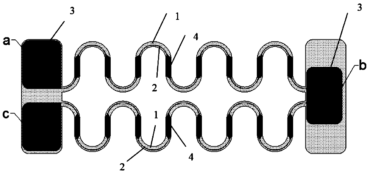
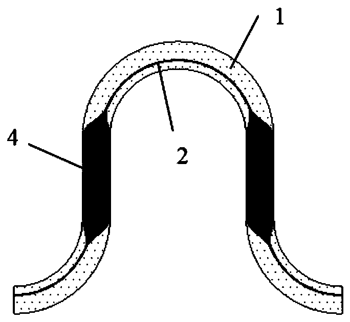
[0073] Embodiment 1: It is an embodiment of the resistive strain sensor with the structure shown in FIG. 1 .

[0074] The thickness of the PI film of the strain sensor is 0.05 mm, the width of the PI film at the arc and straight line sections is 0.05 mm, the average radius is 0.15 mm, and the length of the straight line section is 0.15 mm. The thickness of the gold foil is 100nm, and the bonding layer chromium between the PI film and the PI film is 10nm. The line width of the gold foil in the curved section is 2μm and 2.25μm, which are respectively 0.015mm from the inner edge of PI and 0.015mm from the outer edge of PI; Same width as PI film. The length of the PI on both sides for pasting the measured object is 1.13mm, and the width is 0.4mm.

[0075] Preparation:

[0076] Purchase or spin-coat a polymer film as the substrate 1, and coat a layer of metal film on the substrate 1 to become a composite laminate;

[0077] Making a photolithographic master: cover a layer of phot...

Embodiment 2

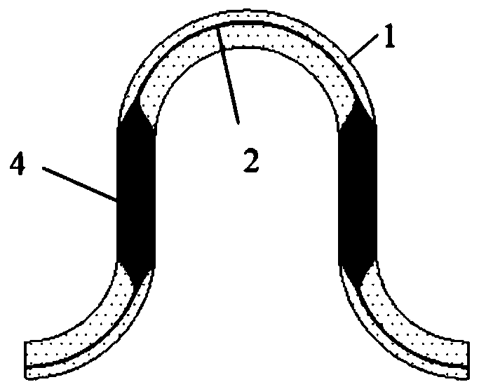
[0079] Example 2: for image 3 An embodiment of a resistive strain sensor of the structure shown.

[0080] The thickness of the PI film of the strain sensor is 0.05 mm, the width of the PI film at the arc and straight line sections is 0.05 mm, the average radius is 0.15 mm, and the length of the straight line section is 0.15 mm. The thickness of the gold foil is 100nm, and the bonding layer chromium between the PI film and the PI film is 10nm. The line width of the gold foil in the curved section is 2μm and 2.25μm, which are respectively 0.015mm from the inner edge of PI and 0.015mm from the outer edge of PI; Same width as PI film. The length of the PI on both sides for pasting the measured object is 1.53mm, and the width is 0.4mm.

[0081] Preparation:

[0082] Purchase or spin-coat a polymer film as the substrate 1, and coat a layer of metal film on the substrate 1 to become a composite laminate;

[0083] Making a photolithographic master: cover a layer of photoresist on...


PUM


Abstract

The invention provides a resistance-type strain sensor and a strain measurement method. The strain sensor can automatically perform temperature compensation during a strain measurement process, and meanwhile improves the sensitivity of strain measurement. The strain sensor comprises strain resistors and a substrate; the strain resistors are fixed on the substrate. The strain sensor is characterized in that the substrate is made from insulating material and is of a curved structure, the substrate at least comprises two rows arranged in parallel, and the end parts are separately connected with apasting end; one ends of the strain resistors on the two-row substrate are connected in series to achieve temperature compensation during a strain measurement process; the axle wires of the strain resistors on the two-row substrate are positioned at different positions of the substrate, to achieve the differences between the resistance variations during the strain measurement process. When in strain measurement, a lead is lead out from each of the two electrical ends of the strain resistors connected in series and the serially connected part in the resistance-type strain sensor to a half bridge measurement circuit and calibrated, and the measurement half bridge outputs voltage to acquire the strain of the substance under test.

Description

technical field [0001] The invention belongs to the technical field of strain sensor design, and in particular relates to a resistive strain sensor with a curved resistance structure and a strain measurement method. The resistive strain sensor can accurately measure super-large-scale strain and can compensate for temperature changes in strain measurement . Background technique [0002] The strain of an object is a very important geometric parameter, and its accurate measurement is of great significance. A strain sensor is a sensor used to measure the strain generated by the deformation of an object under force. There are many kinds of strain sensors, divided according to the principle, there are resistive, capacitive, piezoelectric, inductive and optical, and so on. Resistive strain sensor, its resistive material can be divided into metal, semiconductor, solution, conductive polymer, graphite, etc. [0003] During the test, the strain gauge is firmly pasted on the surface...

Claims


Application Information

Patent Timeline
Patent Type & Authority Applications(China)
IPC IPC(8): G01B7/16
Inventor 苏业旺李爽
Owner INST OF MECHANICS - CHINESE ACAD OF SCI
Why Eureka
Try Eureka