A method and device for automatically finding interference fringes

A technology of interference fringes and fringes, applied in the direction of measuring devices, optical devices, instruments, etc., can solve the problems of cumbersome manual operations, easy collisions in measurement, low-efficiency switching between computers and equipment, etc., and achieve efficient search process and high efficiency.

Active Publication Date: 2020-09-11
CHOTEST TECH INC
View PDF6 Cites 0 Cited by
  • Summary
  • Abstract
  • Description
  • Claims
  • Application Information

AI Technical Summary

Problems solved by technology

[0005] Aiming at the above technical problems, the present invention discloses a method and device for automatically finding interference fringes, which solves the problems of cumbersome manual operations, low efficiency switching between computers and equipment, and easy collisions in measurement

Method used


Image

  • A method and device for automatically finding interference fringes
  • A method and device for automatically finding interference fringes
  • A method and device for automatically finding interference fringes

Examples


Embodiment 1

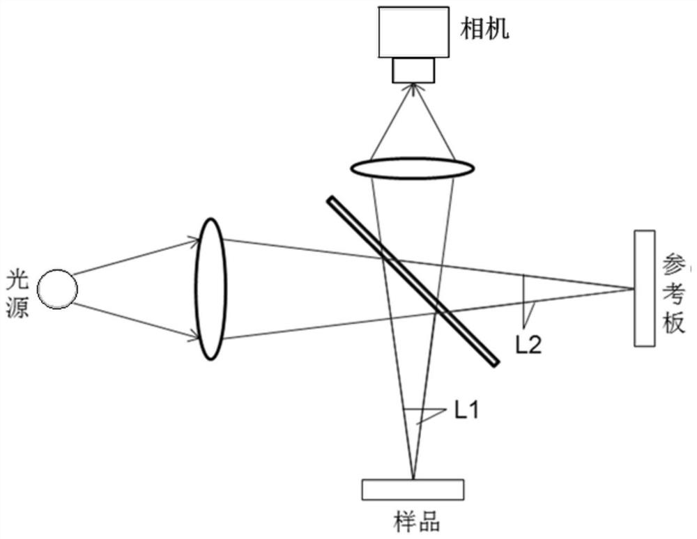
[0054] A device for automatically finding interference fringes, such as Figure 7 As shown, it includes a motion control module, an image acquisition module, and an interference fringe search module. The interference fringe search module includes a fringe feature calculation module, an interference brightest feature detection module, and an interference feature disappearance detection module. The motion control module and the image The acquisition module is connected to drive the image acquisition module to move along the Z direction of the white light interference scanning image, and the image acquisition module is connected to the fringe feature calculation module; the fringe feature calculation module is respectively connected to the interference brightest feature detection module and the interference feature disappearance detection module connect. The modules are described below:

[0055] (1) Motion control module: including the drive motor and the grating, the image acqu...

Embodiment 2

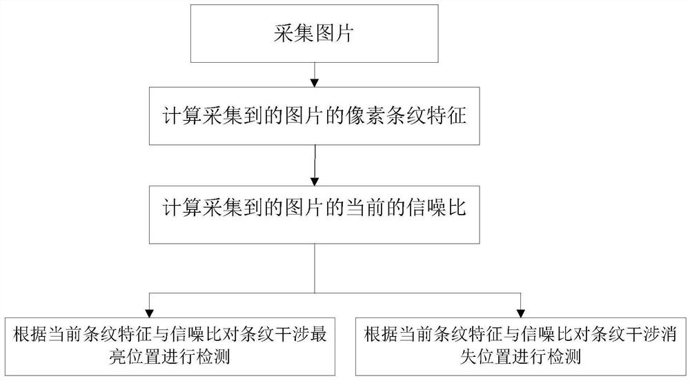
[0062] The device for automatically finding interference fringes in Embodiment 1 adopts the following methods to automatically find interference fringes, including:

[0063] Collect N pictures at equal intervals in the Z direction, where N is an integer greater than or equal to 9;

[0064] Calculate the stripe feature value of each pixel of the collected picture sequence at the sampling position;

[0065] Calculate the signal-to-noise ratio of each pixel fringe for the collected picture sequence at the sampling position;

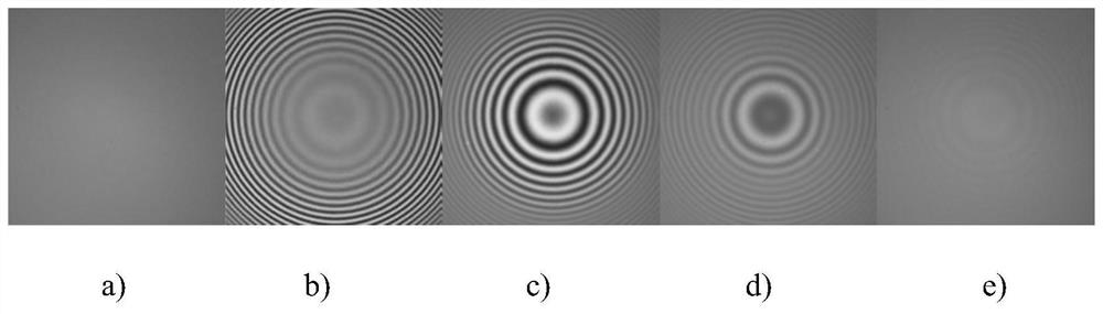
[0066] Detect the brightest position of fringe interference at the sampling position according to the current fringe characteristics and signal-to-noise ratio;


PUM


Abstract

The invention provides a method and device for automatically finding interference fringes. The method includes the following steps that pictures of white light interferometric scanning images are successively collected at equal intervals in the Z direction, continuous N pictures among the collected pictures are selected, and an eigenvalue of a pixel fringe of the image corresponding to the nth-frame picture is calculated; N is an integer greater than or equal to 3; the signal-to-noise ratio of the pixel fringe of the image corresponding to the nth-frame picture is calculated; detection is conducted on the current state according to the current eigenvalue and the signal-to-noise ratio of the pixel fringe of the nth-frame picture; and according to eigenvalues and signal-to-noise ratios of pixel fringes corresponding to the pictures in the different Z directions, the brightest Z-direction position of fringe interference and the Z-direction position of disappearance of fringe interferenceare obtained through detection. According to the technical scheme, by automatically finding and locating to the interference position, the safe and efficient searching process is realized, real-time operation and observation by operators are not required, the time and labor are saved, the efficiency is high, and the safety and reliability are achieved.

Description

technical field [0001] The invention relates to interference fringe detection, in particular to a method and device for automatically finding interference fringes. Background technique [0002] The optical 3D surface profiler is a precision instrument developed on the basis of white light interference scanning technology for the detection of the microscopic topography of the sample surface. With the non-contact scanning method, the 3D measurement of the sample surface with ultra-high repeatability is realized, and the 2D and 3D data representing the surface quality of the sample are obtained. It can be widely used in the measurement and analysis of parameters such as surface roughness and geometric profile of precision components in semiconductor, 3C electronics, ultra-precision processing, optical processing, micro-nano materials, micro-electromechanical and other industries. The surface topography characteristics such as flatness, roughness, waviness, surface profile, sur...

Claims


Application Information

Patent Timeline
Patent Type & Authority Patents(China)
IPC IPC(8): G01B11/25
Inventor 张和君霍阔
Owner CHOTEST TECH INC
Why Eureka
Try Eureka