Benthal deposit collecting system and method

A collection system and sediment technology, applied in the direction of sampling device, test sample preparation, etc., can solve the problems of complicated operation of the collection device, low sampling efficiency, inability to use deep water sampling, etc., and achieve low impact on the underwater environment, convenient operation, small effect

Inactive Publication Date: 2019-06-14
杭州珑亚珀伟科技有限公司
View PDF0 Cites 0 Cited by
  • Summary
  • Abstract
  • Description
  • Claims
  • Application Information

AI Technical Summary

Problems solved by technology

[0005] The purpose of the present invention is to provide a bottom sediment collection system with simple operation, high reliability and high sampling efficiency in order to overcome the shortcomings of the collection device in the prior art, such as complicated operation, low sampling efficiency and inability to be used for deep water sampling and method

Method used


Image

  • Benthal deposit collecting system and method
  • Benthal deposit collecting system and method
  • Benthal deposit collecting system and method

Examples


Embodiment 1

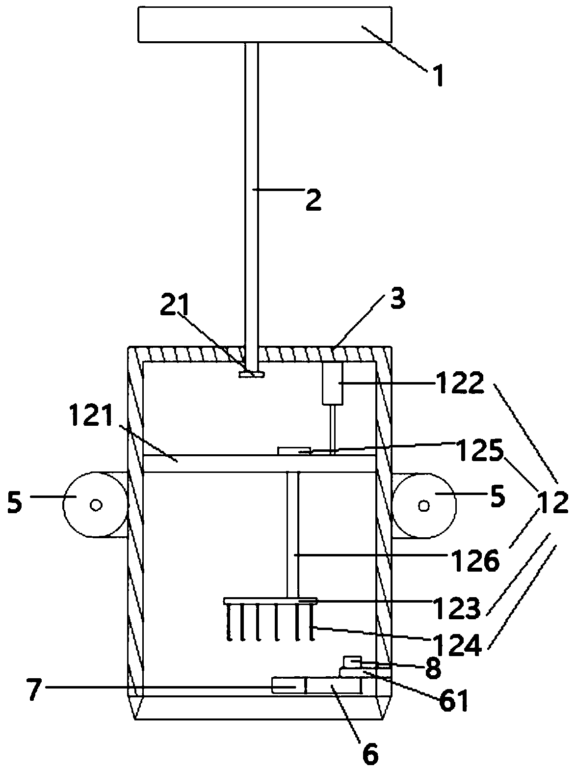
[0041] Such as figure 1 , Figure 5 The shown embodiment is a kind of underwater sediment collecting system, comprises the platform 1 that protrudes out of the ship, is arranged on the column 2 on the platform, and the column 3 that the lower end opening of the column is rotatably connected, is located at the column outer peripheral surface 3 ultrasonic distance measuring sensors 4, 4 drainage tubes 5 arranged on the vertical cylinder along the circumferential direction of the outer peripheral surface of the vertical cylinder, and an arc-shaped box body 6 arranged in the lower part of the vertical cylinder, fixed with the arc-shaped box body Connected arc knife 7; the arc box body is connected with the box body motor 8 fixed on the lower part of the inner wall of the vertical cylinder through the connector 61, and the arc box body is provided with a gauze mechanism 11, and the arc knife is connected with the gauze mechanism , the gauze fixing mechanism 12 is provided in the v...

Embodiment 2

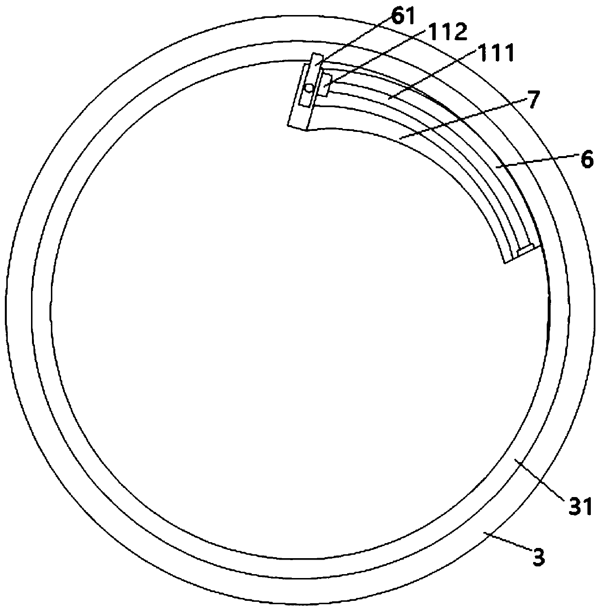
[0054] Embodiment 2 includes all structures and methods of Embodiment 1, such as figure 1 , figure 2 As shown, the gauze mechanism of embodiment 2 includes a flexible shaft 111 arranged in an arc-shaped box body, a gauze wound on the flexible shaft, and an auxiliary motor 112 for driving the flexible shaft to rotate; one end of the flexible shaft passes through the bearing and the arc Shaped box connection, the other end of the flexible shaft is connected to the auxiliary motor, such as Figure 5 As shown, the auxiliary motor is electrically connected to the controller; an elastic rope is arranged on the gauze near the axis of the vertical cylinder, and the gauze is connected with the arc knife;

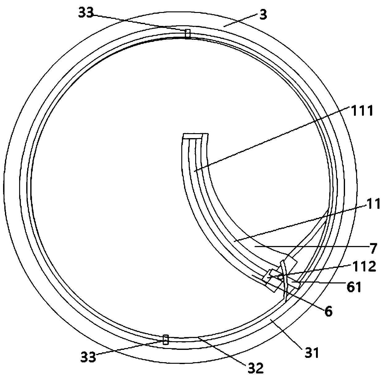
[0055] Such as Figure 4 As shown, it also includes an annular groove 31 located at the lower part of the inner side wall of the vertical cylinder, two guide grooves located on the upper side wall and the lower side wall in the annular groove, and the annular groove is provided wi...

Embodiment 3

[0059] Embodiment 3 includes all structure and method parts of embodiment 1, as figure 1 , Figure 5 As shown, the gauze fixing mechanism of Embodiment 3 includes a bracket 121 arranged in the vertical cylinder, a cylinder 122 arranged at the top of the vertical cylinder, a horizontal plate 123 connected with the telescopic rod of the cylinder, and a horizontal plate 123 arranged on the lower surface of the horizontal plate. 10 hooks 124, each hook is arranged in a circular shape, the support is provided with a rotating motor 125, the rotating motor is connected with the horizontal plate through the vertical bar 126, and the cylinder and the rotating motor are electrically connected with the controller; The avoidance hole of the baffle.

[0060] Steps (6-5) are replaced by the following steps:

[0061] The controller controls the cylinder to drive the bracket to move down until each hook contacts the gauze under the sediment layer, and the controller controls the rotating mo...


PUM


Abstract

The invention discloses a benthal deposit collecting system and method. The benthal deposit collecting system comprises a platform extending out of a ship, a vertical column arranged on the platform,a vertical cylinder with the open lower end, a plurality of ultrasonic ranging sensors arranged on the peripheral face of the vertical cylinder, and a plurality of drainage cylinders arranged on the vertical cylinder and arrayed in the circumferential direction of the peripheral face of the vertical cylinder, wherein the vertical cylinder is rotationally connected with the vertical column; the benthal deposit collecting system further comprises a supporting column arranged on the ship, an L-shaped corbel arranged on the supporting column, and a pallet arranged on the corbel; and a corbel motorused for driving the L-shaped corbel to rotate is arranged in the supporting column, and the corbel motor is electrically connected with a controller. The benthal deposit collecting system has the characteristics that automatic lifting can be achieved, a deposit layer can be taken out from benthos completely, operation is convenient, and the influence on the benthal environment is small.

Description

technical field [0001] The invention relates to the technical field of sampling tools, in particular to an underwater sediment collection system and method with simple operation, high reliability and high sampling efficiency. Background technique [0002] The various sources of sediment deposited on the bottom of the water include suspended matter such as sediment entrained in rivers, rivers, lakes, and sea water; the remains of aquatic organisms and their decomposition products; water pollutants, especially mercury, cadmium, lead, zinc, Heavy metals such as nickel and organic substances with strong adsorption. Through the analysis of the physical, chemical, and biological characteristics of the bottom sediments, as well as the study of the depositional environment, it is possible to find out the types of pollutants in the past, determine the degree of pollution, and determine the location of the pollution source. [0003] At present, the sediment collection device is mainl...

Claims


Application Information

Patent Timeline
Patent Type & Authority Applications(China)
IPC IPC(8): G01N1/08G01N1/12G01N1/28
Inventor 不公告发明人
Owner 杭州珑亚珀伟科技有限公司
Why Eureka
Try Eureka