Voltage-reduction clamping type direct-current circuit breaker suitable for direct-current power grid

A technology of DC circuit breaker and DC power grid, applied in power transmission AC network, emergency protection circuit device, electrical components, etc., can solve the problems of poor rapidity and economy, low capacity of high-voltage DC circuit breaker, etc., and achieve low cost and loss. Low, increase the effect of clearing speed

Inactive Publication Date: 2019-06-14
NORTH CHINA ELECTRIC POWER UNIV (BAODING)
View PDF7 Cites 8 Cited by
  • Summary
  • Abstract
  • Description
  • Claims
  • Application Information

AI Technical Summary

Problems solved by technology

[0004] The purpose of the present invention is to overcome the shortcomings of low capacity, rapidity and poor economy of the current high voltage DC circuit breaker

Method used


Image

  • Voltage-reduction clamping type direct-current circuit breaker suitable for direct-current power grid
  • Voltage-reduction clamping type direct-current circuit breaker suitable for direct-current power grid
  • Voltage-reduction clamping type direct-current circuit breaker suitable for direct-current power grid

Examples


Embodiment Construction

[0015] The technical solutions in the embodiments of the present application will be clearly and completely described below in conjunction with the drawings in the embodiments of the present application.

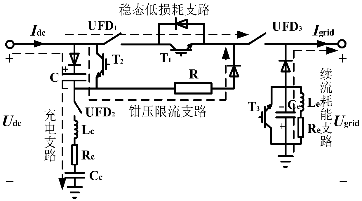
[0016] A schematic diagram of the topological structure of a step-down clamping DC circuit breaker suitable for DC power grids is shown in figure 1 As shown, including the clamp current limiting branch, charging branch, steady-state low loss branch and freewheeling energy consumption branch;

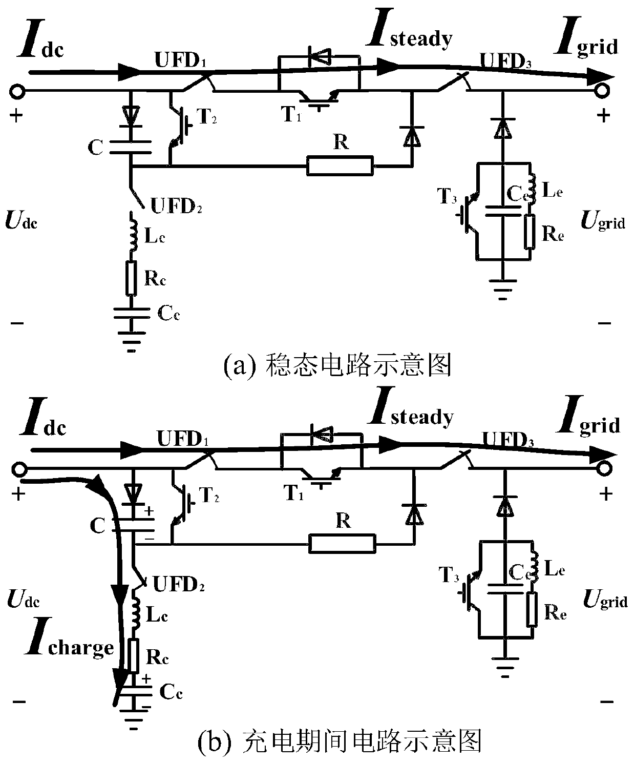
[0017] figure 2 The schematic diagram of the charging stage is shown. When the charging starts, the isolation switch UFD2 is opened to connect the voltage dividing capacitor Cc, the charging resistor Rc and the charging inductance Lc into the charging circuit. At this time, the DC line starts to charge the clamping capacitor C, and the DC current Idc is shunted as There are two parts of steady state current Isteady and charging current Icharge, such as figure 2 (b) shown. Since th...


PUM


Abstract

The invention relates to a voltage-reduction clamping type direct-current circuit breaker suitable for a direct-current power grid, and belongs to the technical field of multi-end direct-current and direct-current power grids. A topology can be divided into four branches, comprising a voltage clamping and current limiting branch circuit, a charging branch circuit, a steady-state low-loss branch circuit and a follow-current energy consumption branch circuit; and a capacitor, an isolation switch, a resistor, an inductor and other devices are required to be used. According to the voltage-reduction clamping type direct-current circuit breaker, a pre-charging capacitor is connected to a fault loop, and by virtue of the clamping voltage generated by the charging process and the current increaselimiting effect, a grid side circuit voltage is reduced to be zero, so that a direct current fault is eliminated.

Description

technical field [0001] The invention relates to a step-down clamping type DC circuit breaker suitable for a DC power grid, which belongs to the field of multi-terminal DC and DC power grids. Background technique [0002] Flexible DC transmission is a new generation of power transmission technology that can be used in grid interconnection and renewable energy access and other fields. The multi-terminal DC and DC grid based on flexible DC transmission is one of the important directions for the development and transformation of the future grid. The Zhangbei project currently under construction is a landmark project of DC transmission in my country, and the future DC grid project will develop in the direction of more terminals, larger capacity, and higher reliability. In long-distance DC transmission projects, overhead line transmission is the main transmission mode. The overhead line is exposed to the outside world, and the risk of failure is high; in addition, the development...

Claims


Application Information

Patent Timeline
Patent Type & Authority Applications(China)
IPC IPC(8): H02H7/26H02J3/36
CPCY02E60/60
Inventor 贾秀芳李嘉龙赵西贝许建中赵成勇
Owner NORTH CHINA ELECTRIC POWER UNIV (BAODING)
Why Eureka
Try Eureka