Main spindle device and machine tool

A kind of spindle device and spindle technology, applied in the direction of drive device, feeding device, positioning device, etc., can solve the problems of small heat generation, spindle position deviation, moving spindle and bearing, etc.

Active Publication Date: 2019-06-18
TOSHIBA MASCH CO LTD
View PDF16 Cites 3 Cited by
  • Summary
  • Abstract
  • Description
  • Claims
  • Application Information

AI Technical Summary

Problems solved by technology

In non-contact bearings, compared with contact bearings, it has the following characteristics: the friction coefficient of the bearing is small and the heat generation is small; on the other hand, the bearing rigidity is low, and the main shaft is easy to move under the external force. The gap between the main shaft and the

Method used


Image

  • Main spindle device and machine tool
  • Main spindle device and machine tool
  • Main spindle device and machine tool

Examples


no. 1 Embodiment approach ]

[0034] refer to Figure 1 to Figure 5 , the spindle device 100 of the first embodiment and the machine tool 200 including the spindle device 100 will be described.

[0035] (Outline of spindle unit and machine tool)

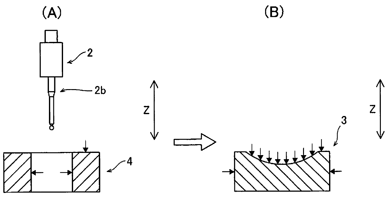
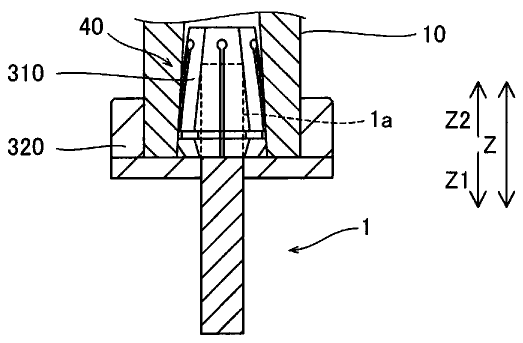
[0036] Such as figure 1 Shown, the main shaft device 100 is by the main shaft 10 (referring to figure 2 ) is a device for rotating and driving the tool 1 attached to one end of the main shaft 10 around the central axis to process the workpiece 3 as the workpiece. The spindle device 100 is assembled in the machine tool 200 and relatively moves with respect to the workpiece 3 by the moving mechanism 110 included in the machine tool 200 . The machine tool 200 is a numerical control (NC) machine tool, which controls the relative movement (position and speed) of the tool 1 and the workpiece 3 by means of numerical information, and executes a series of actions related to machining by means of the program 132 . Specifically, the machine tool 200 is a machining cent...

no. 2 Embodiment approach ]

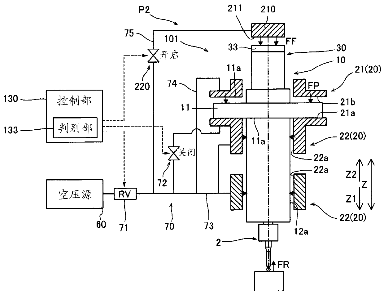
[0116] Next, refer to Figure 8 and Figure 9 , the spindle device 101 of the second embodiment will be described. In the second embodiment, unlike the first embodiment in which the pressure supply to the other side axial bearing surface 21b of the axial bearing portion 21 is switched off to switch to the measurement state P2, the counter spindle 10 is set at The structure of the biasing portion 210 for biasing in the axial direction will be described. In addition, in the second embodiment, the structure other than the main shaft device 101 is the same as that of the above-mentioned first embodiment, so description thereof will be omitted. In addition, in 2nd Embodiment, the same code|symbol is attached|subjected to the same structure as said 1st Embodiment, and description is abbreviate|omitted.

[0117] Such as Figure 8 As shown, in the spindle device 101 of the second embodiment, a force applying unit 210 is provided, and the force applying unit 210 is in the measureme...


PUM


Abstract

A main spindle device is provided with: a main spindle; a non-contact bearing that rotatably supports the main spindle in a non-contact manner; a drive unit; and a tool holding part which is providedat one end of the main spindle and detachably holds the tool or a contact sensor. The non-contact bearing is configured so that, when the contact sensor is attached, the non-contact bearing can be switched to a measurement state in which the movement of the main spindle is suppressed by supporting the main spindle in a contact state.

Description

technical field [0001] The present invention relates to a spindle device and a machine tool, and more particularly to a spindle device and a machine tool including a spindle to which a sensor for measuring a workpiece can be attached instead of a tool. Background technique [0002] Conventionally, there is known a spindle device including a spindle to which a sensor for measuring a workpiece can be attached instead of a tool. Such a spindle device is disclosed in, for example, Japanese Patent Application Laid-Open No. 2006-326804. [0003] The aforementioned Japanese Patent Application Laid-Open No. 2006-326804 discloses a spindle device including a spindle, a bearing for rotatably supporting the spindle, a motor for rotationally driving the spindle, and a tool clamping mechanism provided at the front end of the spindle. At the front end of the main shaft, one of the tool for machining the workpiece and the measuring head for measuring the diameter of the processed part of ...

Claims


Application Information

Patent Timeline
IPC IPC(8): B23B19/02B23Q17/20B23Q17/00
CPCF16C2322/39B23Q5/54B23Q5/043B23Q5/32B23Q17/20B23Q3/15546F16C32/064
Inventor 秋山贵信槻田丰伊谷慎也
Owner TOSHIBA MASCH CO LTD
Why Eureka
Try Eureka