Buckle structure for connecting integrated parts

A technology of snap-fit ​​structure and integrated components, applied in directions such as fuel and air inlets, can solve problems such as increased cost, stress concentration at the vacuum chamber connection, fracture failure at the connection, etc., to facilitate disassembly and installation, avoid stress concentration, improve The effect of strength and reliability

Pending Publication Date: 2019-06-18
MANNHUMMEL FILTER SHANGHAI
View PDF0 Cites 0 Cited by
  • Summary
  • Abstract
  • Description
  • Claims
  • Application Information

AI Technical Summary

Problems solved by technology

Since the intake manifold housing 102 is fixed on the engine flange surface, when the engine is running, the intake manifold housing 102 will be driven to vibrate greatly, and the vacuum chamber 101 will be affected by its own gravity and will be in contact with the intake air. The connection of the manifold housing 102 produces a similar lever effect, and the other end of the vacuum chamber 101 is connected to other components through a hose, which causes stress concentration on the connection of the vacuum chamber, resulting in the risk of fracture and failure of the connection. The connection between the plug nut 103 and the fastening bolt 104 has a shock absorption effect, and buffers the stress of the intake manifold shell on the vacuum chamber, but increases the cost

Method used


Image

  • Buckle structure for connecting integrated parts
  • Buckle structure for connecting integrated parts
  • Buckle structure for connecting integrated parts

Examples


Embodiment Construction

[0022] The present invention will be described in detail below in conjunction with the accompanying drawings and specific embodiments.
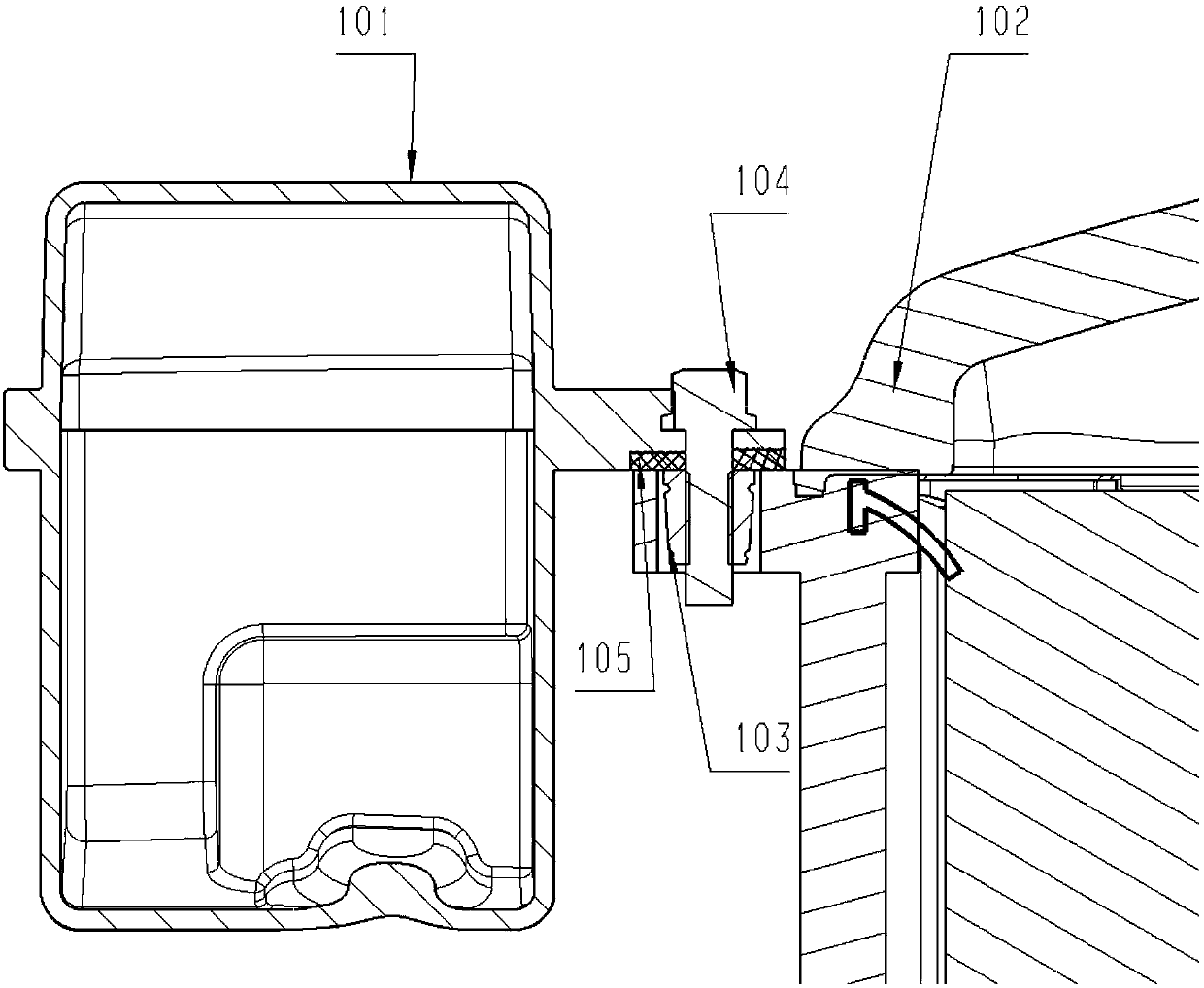
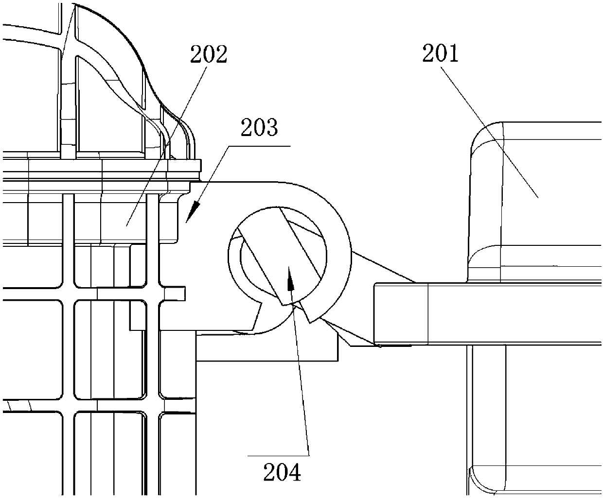
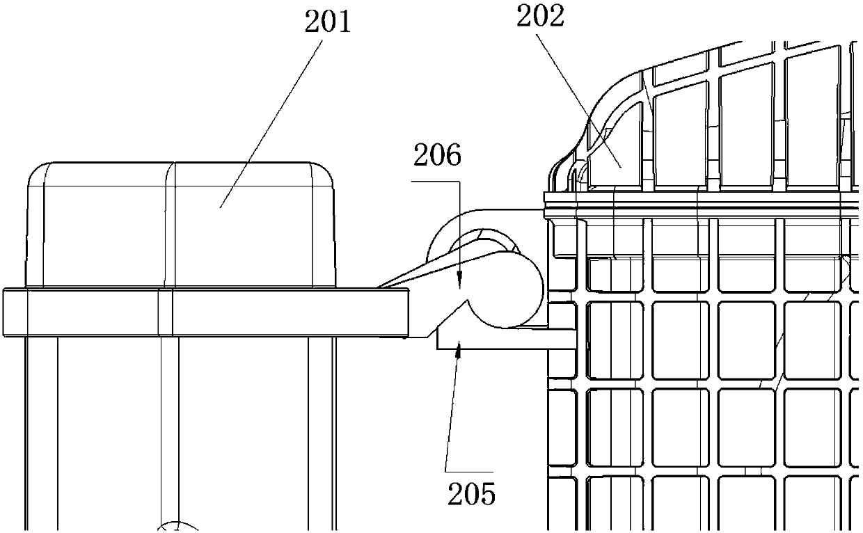
[0023] A snap-fit ​​structure for connecting integrated components such as figure 2 , 3 As shown, it is used to connect the intake manifold housing 202 and the vacuum chamber housing 201, including the first card slot 203 and the second card slot 205 arranged on both sides of the intake manifold housing 202, and the vacuum chamber housing The first gear button 204 and the second gear button 206 on both sides of the body 201, the first card slot 203 is provided correspondingly to the first gear button 204, the second card slot 205 is correspondingly arranged to the second gear button 206, and the first card slot 203 is provided correspondingly. The first gear buckle 204 is inserted, and the second gear buckle 206 is engaged with the second locking slot 205 .

[0024] As a preferred technical solution, the first card slot 203 is a circular c...


PUM

PropertyMeasurementUnit
Diameteraaaaaaaaaa
Opening widthaaaaaaaaaa

Abstract

The invention relates to a buckle structure for connecting integrated parts. An air inlet manifold shell and a vacuum cavity shell are connected through the buckle structure. The buckle structure comprises a first clamping groove, a second clamping groove, a first resisting buckle and a second resisting buckle. The first clamping groove and the second clamping groove are formed in the two sides ofthe air inlet manifold shell, and the first resisting buckle and the second resisting buckle are arranged on the two sides of the vacuum cavity shell. The first clamping groove and the first resisting buckle are correspondingly arranged, and the second resisting buckle and the second clamping groove are correspondingly arranged. The first resisting buckle is inserted into the first clamping groove, and the second resisting buckle and the second clamping groove are connected with each other in a clamped mode. Compared with the prior art, the buckle structure has the advantages that the firmness of the connection between the air inlet manifold shell and the vacuum cavity shell is effectively achieved, and the phenomenon that when an engine runs, the connection breakage damage is caused by the stress concentration which is generated due to the vibration is avoided. By the adoption of the buckle structure, the concentrated stress generated by the hard connection of bolts, thermal plugs and the like can be well avoided, a certain buffering protection effect on the connection between the two parts exists, and the strength and the reliability of the connection between the two parts are improved.

Description

technical field [0001] The invention relates to a connection structure, in particular to a buckle structure for connecting integrated components. Background technique [0002] With the rapid development of automobile technology and fierce competition in the automobile market, OEMs have increasingly stringent requirements on the space layout and cost of parts around the car engine, and the number of parts around the car engine is also increasing with the improvement of engine technology , the layout around the engine is becoming more and more complex, the space in the engine compartment is getting smaller and smaller, and the requirements for engine compactness are further improved. For example: the plastic vacuum tank and the air filter are integrated and installed on the intake manifold. Since the intake manifold is installed on the engine, this not only optimizes the space layout of the engine compartment, but also shortens the airflow pipeline and reduces the airflow in t...

Claims


Application Information

Patent Timeline
IPC IPC(8): F02M35/10
Inventor 史菁菁
Owner MANNHUMMEL FILTER SHANGHAI
Why Eureka
Try Eureka