A mobile network-based smart meter remote recovery auxiliary device and method

A smart meter and mobile network technology, applied in the electronic field, can solve the problems of smart meter closing and repowering, and achieve the effects of strong anti-interference ability, saving transportation costs, and simple operation

Active Publication Date: 2021-07-13
CHINA THREE GORGES UNIV
View PDF8 Cites 0 Cited by
  • Summary
  • Abstract
  • Description
  • Claims
  • Application Information

AI Technical Summary

Problems solved by technology

At this stage, if the remote power restoration command fails to be issued, it takes a long time for the liaison officer to arrive at the scene and hold the handheld device to turn on the smart meter and restore power

Method used


Image

  • A mobile network-based smart meter remote recovery auxiliary device and method
  • A mobile network-based smart meter remote recovery auxiliary device and method
  • A mobile network-based smart meter remote recovery auxiliary device and method

Examples


Embodiment 1

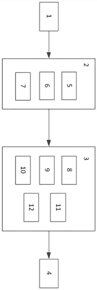
[0023] like figure 1 As shown, a mobile network-based smart meter remote power restoration auxiliary device includes a handheld device 1, a power restoration signal receiving device 2, a power restoration signal transmitting device 3 and a smart meter 4, and the handset 1 and power restoration signal receiving device The device 2 is connected in communication, and the complex electrical signal receiving device 2 is connected in communication with the complex electrical signal transmitting device 3, and the complex electrical signal transmitting device 3 is connected to the smart meter 4;

[0024] Described complex electric signal receiving device 2 comprises microcontroller A5, GSM short message module A6 and infrared receiving circuit 7, and the input end of microcontroller A5 is connected with infrared receiving circuit 7;

[0025] Described complex electrical signal transmitting device comprises microcontroller B8, GSM short message module B9, infrared emission circuit 10, ...

Embodiment 2

[0039] When the power supply of the power supply of the power recovery transmitter adopts an adapter, the power recovery signal transmitter 3 can be installed next to the smart meter, without the need for personnel to go to the scene to realize power recovery; Distributed to the customer, the user only needs to point at the smart meter 4 and press a button, and the electricity can also be restored.

Embodiment 3

[0041] like Figure 4 It is an infrared transmitting circuit, in which a piece of ICl high-speed CMOS type 4-2 input "NAND" gate 74HC00 integrated circuit is used to form a low-frequency oscillator as a coded signal (f1), and an IC2 555 circuit is used as a carrier oscillation device, the oscillation frequency is f0 (38kHz). f1 modulates f0, so the waveform of pin ③ of IC2 is a discontinuous carrier wave, which is sent to the space through the infrared light-emitting diode. The 555 circuit is selected as the carrier oscillator. The modulation working principle of the circuit is to use the 555 to generate a 38kHz square wave signal, and then use the reset terminal ④ of the 555 as the modulation terminal, that is, when the ④ pin is high, the 555 is a conventional square wave signal. Wave oscillator; when pin ④ is low, pin ③ of 555 is low. ④ The modulation signal of the foot is obtained by the low-frequency oscillator of the NAND gate of ICl.


PUM


Abstract

The invention discloses a remote power recovery auxiliary device and method for a smart meter based on a mobile network. , the electrical recovery signal receiving device is communicatively connected to the electrical recovery signal transmitting device, and the electrical recovery signal transmitting device is connected to a smart meter. The present invention truly realizes the remote fast power recovery and the stable transmission of the power recovery signal, and has strong anti-interference ability. The liaison officer does not need to arrive at the scene, but only needs the staff of the power supply station to issue a power restoration command, which not only saves transportation costs, but also avoids complaints caused by long power restoration time or repeated power restoration failures.

Description

technical field [0001] The invention relates to the field of electronic technology, in particular to a mobile network-based remote recovery auxiliary device for smart meters. Background technique [0002] With the gradual completion of the goal of full coverage of smart meters and the widespread application of new electronic payment channels, measures need to be taken to further control the risk of electricity charges; Management system, including remote real-time fee control system. At this stage, if the remote power restoration command fails to be issued, it takes a long time for the liaison officer to arrive at the scene with a handheld device to turn on the smart meter and restore power. It is necessary to design a set of promotional and popular remote fee-controlled power recovery auxiliary device, so that the system can recover power independently or the user can complete the power recovery operation safely and quickly. Contents of the invention [0003] The purpos...

Claims


Application Information

Patent Timeline
Patent Type & Authority Patents(China)
IPC IPC(8): G05B19/042G07F15/06G08B3/10G08C23/04H04W4/14
Inventor 程杉徐敬伟魏昭彬
Owner CHINA THREE GORGES UNIV
Why Eureka
Try Eureka