A method of determining lumen image branch points and branch segments

A branch point, lumen technology, applied in image data processing, instruments, computer-aided planning/modeling, etc., can solve the problems affecting the consistency of doctors' surgical operations, inconvenient surgical operations, and not reflecting the multi-view three-dimensional shape of the lumen, etc. question

Active Publication Date: 2019-06-18
杭州国节能源技术有限公司
View PDF8 Cites 6 Cited by
  • Summary
  • Abstract
  • Description
  • Claims
  • Application Information

AI Technical Summary

Problems solved by technology

However, endoscopy does not meet the observation needs of doctors, as shown in Figure 1 As shown in : ①The image of the inner cavity is presented on the monitor, and the doctor needs to constantly move his sight between the surgical site and the monitor, which affects the continuity of the doctor's operation and is prone to fatigue
② A single endoscope observes the local area. If the doctor needs to observe a large area, multiple endoscopes will intervene in the human body at the same time, which not only increases the burden on the patient but also increases the burden on the endoscope cable, transmitter / receiver, interventional sleeve, etc. The degree of complexity and cumbersomeness; ③Sometimes assistants are needed to assist in holding and moving multiple endoscopes to cooperate with the doctor's observation, which brings inconvenience to the doctor's operation
[0004]The above solutions are still in the trial stage, and there are still some things to improve: ①The current orientation tracking technology needs to wear a transmitter or a marker on the doctor's head, increasing the ②The image of the inner cavity is a two-dimensional image, which does not reflect the multi-view three-dimensional shape of the inner cavity; Corrects the projected image so that an undistorted image of the lumen is seen on the patient surface

Method used


Image

  • A method of determining lumen image branch points and branch segments
  • A method of determining lumen image branch points and branch segments
  • A method of determining lumen image branch points and branch segments

Examples


specific Embodiment 1

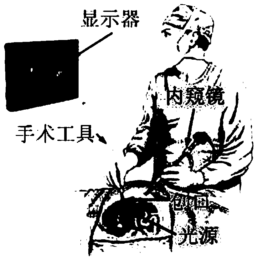
[0043] This embodiment is an embodiment of the method for observing the inner cavity through virtual and transparent projection of the body surface in minimally invasive surgery.

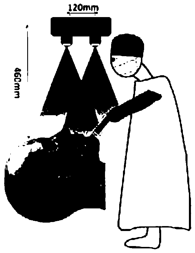
[0044] In the minimally invasive surgery in this embodiment, the body surface projection virtual transparent observation method for the inner cavity, the corresponding body surface projection system is as follows: Figure 4 As shown, the technical roadmap of this method is as follows Figure 5 shown, including the following steps:

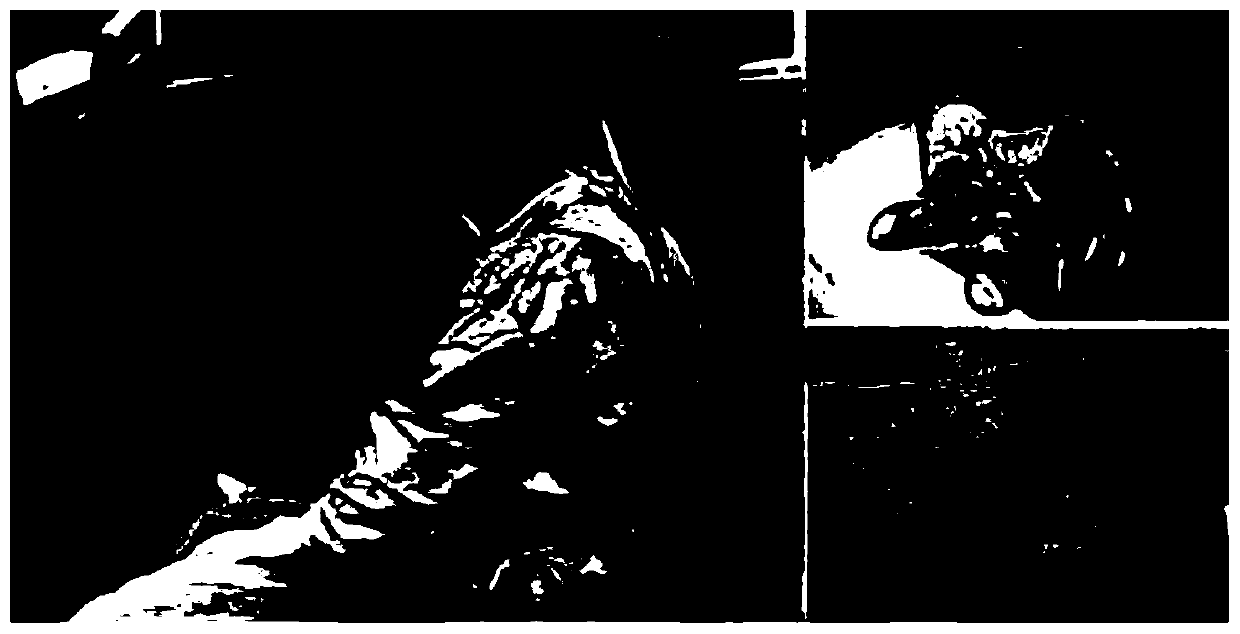
[0045] Step a, Kinect doctor's viewing angle tracking, used to determine the doctor's current head position and visual angle;

[0046] Step b, PTAM three-dimensional modeling of the inner cavity, PTAM is Parallel Tracking and Mapping, which is used to generate a three-dimensional model of the inner cavity that can rotate with the doctor's perspective described in step a;

[0047] Step c. Generating a sequence of projection images of the patient's body surface, and pro...

specific Embodiment 2

[0048] This embodiment is an embodiment of the Kinect doctor's perspective tracking method.

[0049] The Kinect doctor's angle of view tracking method of the present embodiment can exist independently, and specific embodiment one can be further limited again; The Kinect doctor's angle of view tracking method, such as Figure 6 shown, including the following steps:

[0050] Step a1, select the depth data of the pupil and the tip of the nose as key points, and establish a mathematical model of the doctor's perspective;

[0051] Step a2, use the Kalman filter to predict the doctor's perspective and correct the tracking data;

[0052] Step a3, analyzing the orientation relationship among the Kinect, the doctor's head, the patient's body surface, the patient's inner cavity, and the projector, unifying the coordinate system, and designing the parameters of the patient's body surface projection system.

specific Embodiment 3

[0053] This embodiment is a Kalman filter embodiment.

[0054] The Kalman filter of the present embodiment can exist alone, and can be further limited to the second embodiment; the Kalman filter is specifically:

[0055] In a frame of Kinect data at time t, define its Kalman filter state vector X t and the observation vector Z t for:

[0056] x t =(x(t),y(t),z(t),v x (t), v y (t), v z (t))

[0057] Z t =(x(t),y(t),z(t))

[0058] Among them, x(t), y(t) and z(t) are the three-dimensional coordinates of the nose tip center, v x (t), v y (t) and v z (t) is the velocity of the nose tip center;

[0059] Accordingly, the Kalman system equation is:

[0060] x t+1 =AX t +BU t +GW t

[0061] Z t+1 =HX t +V t

[0062] Among them, A is the state matrix, B is the control matrix, which is approximately 0 when the facial movement has no control amount, G is the driving matrix, H is the observation matrix, U t is the control vector, W t is x t Kinect measurement error...


PUM


Abstract

The invention discloses a method for determining branch points and branch segments of a lumen image, and belongs to the technical fields of medicine, three-dimensional imaging, digital image processing and the like. The method comprises the following steps: firstly, according to the characteristic that branch points are three or four blood vessel joint points, making a circle by taking each single-pixel blood vessel feature point as a circle center; judging whether a circumferential point set meets two conditions at the same time, wherein under the condition of meeting, forming a quasi-branchpoint neighborhood bya plurality of adjacent single-pixel blood vessel feature points, taking the sub-pixel center of the quasi-branch point neighborhood as a branch point, after the branch point neighborhood is finally determined, detecting a branch segment alongadjacent pixels with the branch point neighborhood as the starting point, if another branch point neighborhood is met, judging the branch segment as a complete branch segment, and otherwise, judging the branch segment as a half branch segment. The method provided by the invention not only can avoid the problem that the interruption point is misjudged as the branch point, but also can avoid the problem that a small amount of other micro features in the lumen are misjudged as the branch point.

Description

technical field [0001] The invention discloses a method for determining a branch point and a branch segment of an inner cavity image, which belongs to the technical fields of medicine, three-dimensional imaging, digital image processing, and the like. Background technique [0002] Compared with traditional open surgery, minimally invasive surgery has the advantages of small incision, less pain, and faster healing. It caters to the aesthetic concept of modern people, so it is increasingly popular and used in some abdominal and cranial cavity surgeries. At present, the main observation mode of minimally invasive surgery is endoscopy. The endoscope uses multiple pinhole cameras and a xenon lamp light source to capture images of the inflated lumen, which are displayed on the monitor for doctors to observe. At present, the most advanced endoscopes can obtain very high-quality images of the lumen, and then the positioning technology of surgical equipment can be derived from the i...

Claims


Application Information

Patent Timeline
Patent Type & Authority Applications(China)
IPC IPC(8): G06T19/00A61B34/20A61B34/10
Inventor 吴海滨汪颖代启鹏王森于晓洋徐恺阳
Owner 杭州国节能源技术有限公司
Why Eureka
Try Eureka