Automatic winding device for reactor coil

A technology of winding device and reactor, which is applied in coil manufacturing, inductance/transformer/magnet manufacturing, circuits, etc. It can solve the problems affecting the quality of coil winding, wire pressing, and inconvenient demoulding, etc., and achieves good clamping effect, Easy demoulding and lower production cost

Pending Publication Date: 2019-06-18
河南合瑞电气有限公司
View PDF1 Cites 6 Cited by
  • Summary
  • Abstract
  • Description
  • Claims
  • Application Information

AI Technical Summary

Problems solved by technology

[0004] The coil molds used in traditional coil winding are generally made of wood and hard aluminum to form the required size and shape, such as a cylindrical or square cylindrical structure with a fixed shape. Because of its fixed shape and the wires are close to the coil mold Winding, it is very inconvenient to demould after the coil winding is completed; in addition, in the prior art, the wire reel is generally placed on a pay-off rack at a fixed position to pay off the wire. When winding, if the pay-off rack is fixed at a position Moving or moving in any direction at will will easily cause the wire to be pressed on the coil mold, which will affect the coil winding quality

Method used


Image

  • Automatic winding device for reactor coil
  • Automatic winding device for reactor coil
  • Automatic winding device for reactor coil

Examples


Embodiment Construction

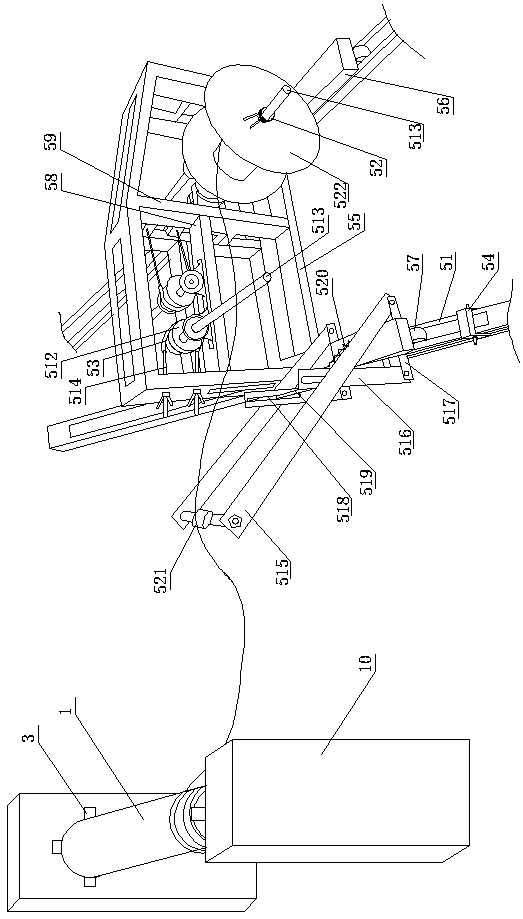
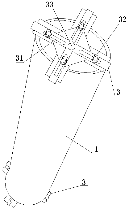
[0031] Such as Figure 1 to Figure 9 As shown, the automatic winding device of a kind of reactor coil of the present invention comprises a pay-off mechanism and a winding mechanism, and the pay-off mechanism includes a pay-off rack and a wire reel 522, and the wire reel 522 is installed on the wire reel shaft of the pay-off rack, The spool shaft 513 is also provided with a clamp 52 for preventing the spool from falling off. The winding mechanism includes a winding machine 10 and a winding tool. The winding machine 10 is provided with two opposite tops 101. The winding tool is installed on Between the two tops 101; a guide rail 51 is installed on the ground at the bottom of the pay-off rack, and the guide rail 51 is arranged parallel to the axis of the top 101. The pay-off rack is slidably connected in the guide rail 51 by a pulley 57 arranged at the bottom of the pay-off rack, and the guide rail 51 is provided with a locking slider 54 for locking the pulley, the locking slider...


PUM


Abstract

The invention discloses an automatic winding device of a reactor coil, which comprises a pay-off mechanism and a winding mechanism, wherein the pay-off mechanism comprises a pay-off rack and a wire coil, the wire coil is arranged on the pay-off rack, the winding mechanism comprises a winding machine and a winding tool, and the winding tool is arranged between two tips of the winding machine; a guide rail is arranged on the ground at the bottom of the pay-off rack and is parallel to the axis of the tip; the winding tool comprises an elastic die, an inner supporting plate and a cross, the elastic die is cylindrical, and an adjusting seam is axially formed on the elastic die; the two inner supporting plates are respectively arranged at two ends of the elastic die and are clamped on the innersurface of the elastic die; the number of the cross is two, and the elastic die is clamped between the two crosses. The wire coil can translate in the direction parallel to the axial direction of thecoil along with the winding of the wire during paying off, so that the wire pressing is effectively prevented; and after the coil is wound and shaped, the wire coil can be quickly demolded, so that the production efficiency can be effectively improved.

Description

technical field [0001] The invention relates to the technical field of reactor production, in particular to an automatic winding device for reactor coils. Background technique [0002] Reactors are mainly used in power systems to limit short-circuit current, reactive power compensation and phase shifting, and are inductive high-voltage electrical appliances. The reactor is generally in the form of a wire wound into a solenoid, which is called an air-core reactor. Sometimes in order to make the solenoid have greater inductance, an iron core is inserted into the solenoid, which is called an iron core reactor. With the acceleration of my country's power grid construction, the expansion of scale, and the increasing load of electricity, the role of reactors in the power system is becoming more and more important, and the demand is also increasing. It is imperative to improve the production efficiency of reactors. [0003] Reactor production includes processes such as winding, so...

Claims


Application Information

Patent Timeline
Patent Type & Authority Applications(China)
IPC IPC(8): H01F41/06H01F41/096H01F41/098
Inventor 崔广磊崔占辉
Owner 河南合瑞电气有限公司
Why Eureka
Try Eureka