High-isolation three-frequency four-unit MIMO antenna

A high-isolation, four-element technology, applied in the directions of antenna arrays, antennas, and antenna couplings that are powered separately, can solve problems such as low isolation, large size of four-element MIMO antennas, and narrow bandwidth

Inactive Publication Date: 2019-06-18
CHONGQING UNIV OF POSTS & TELECOMM
View PDF3 Cites 9 Cited by
  • Summary
  • Abstract
  • Description
  • Claims
  • Application Information

AI Technical Summary

Problems solved by technology

The currently researched four-element MIMO antenna is large in size and narrow in bandwidth, unable to cover more frequency bands, and has low isolation, which is difficult to meet the requirements of miniaturized terminals

Method used


Image

  • High-isolation three-frequency four-unit MIMO antenna
  • High-isolation three-frequency four-unit MIMO antenna
  • High-isolation three-frequency four-unit MIMO antenna

Examples


Embodiment Construction

[0022] specific implementation

[0023] In order to make the purpose, technical solution and advantages of the present invention clearer, the present invention will be further described in detail below in conjunction with the accompanying drawings.

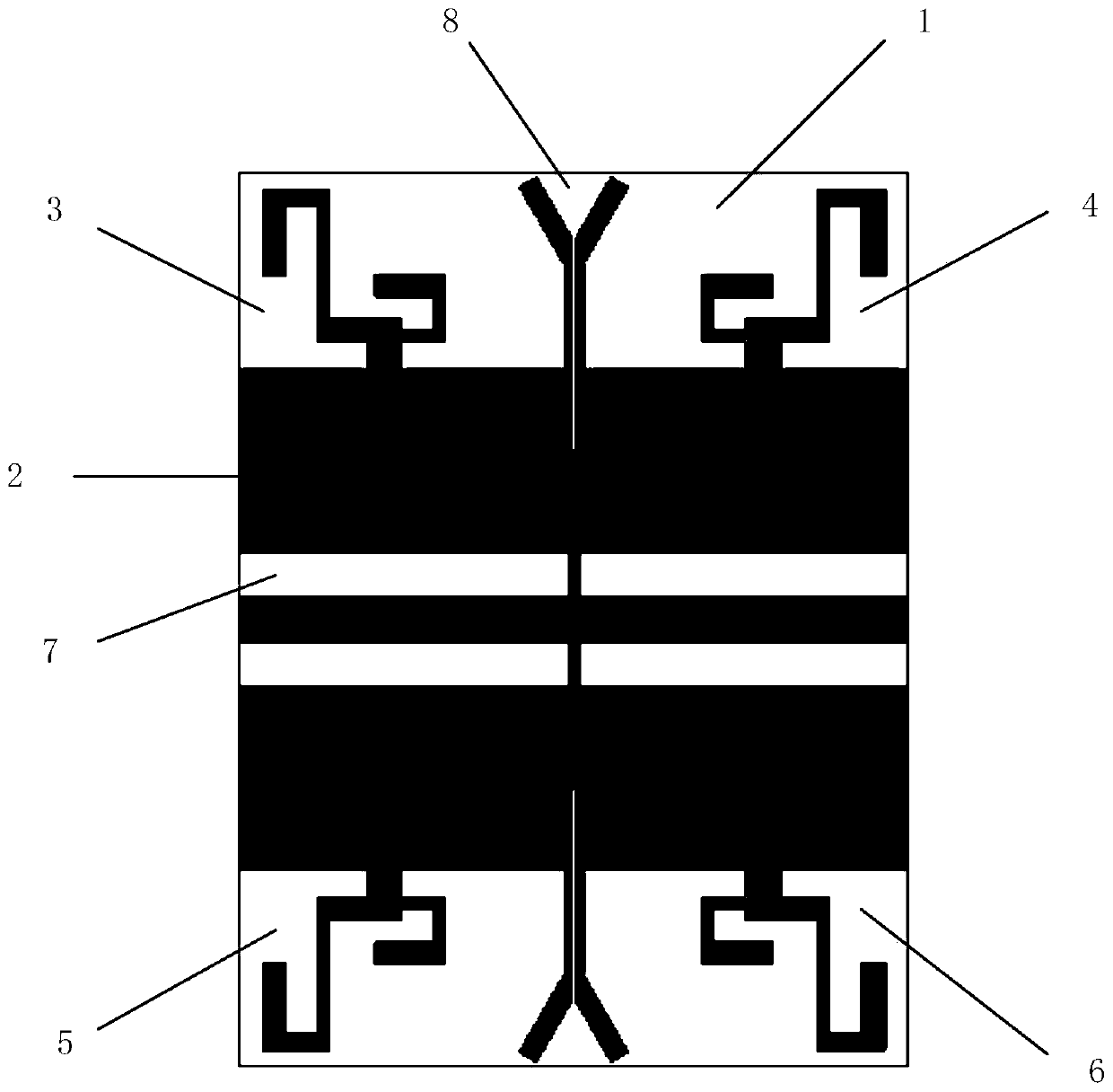
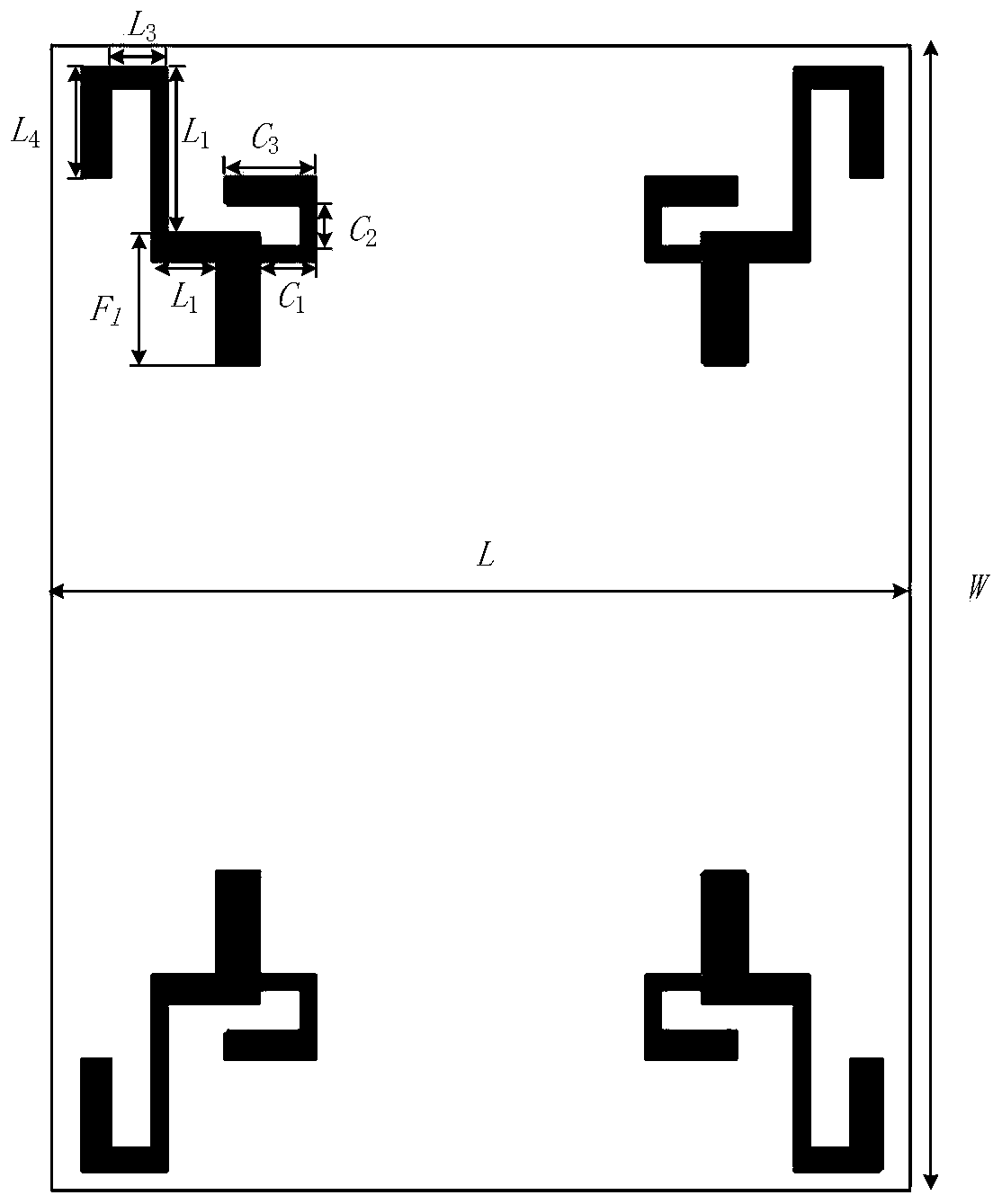
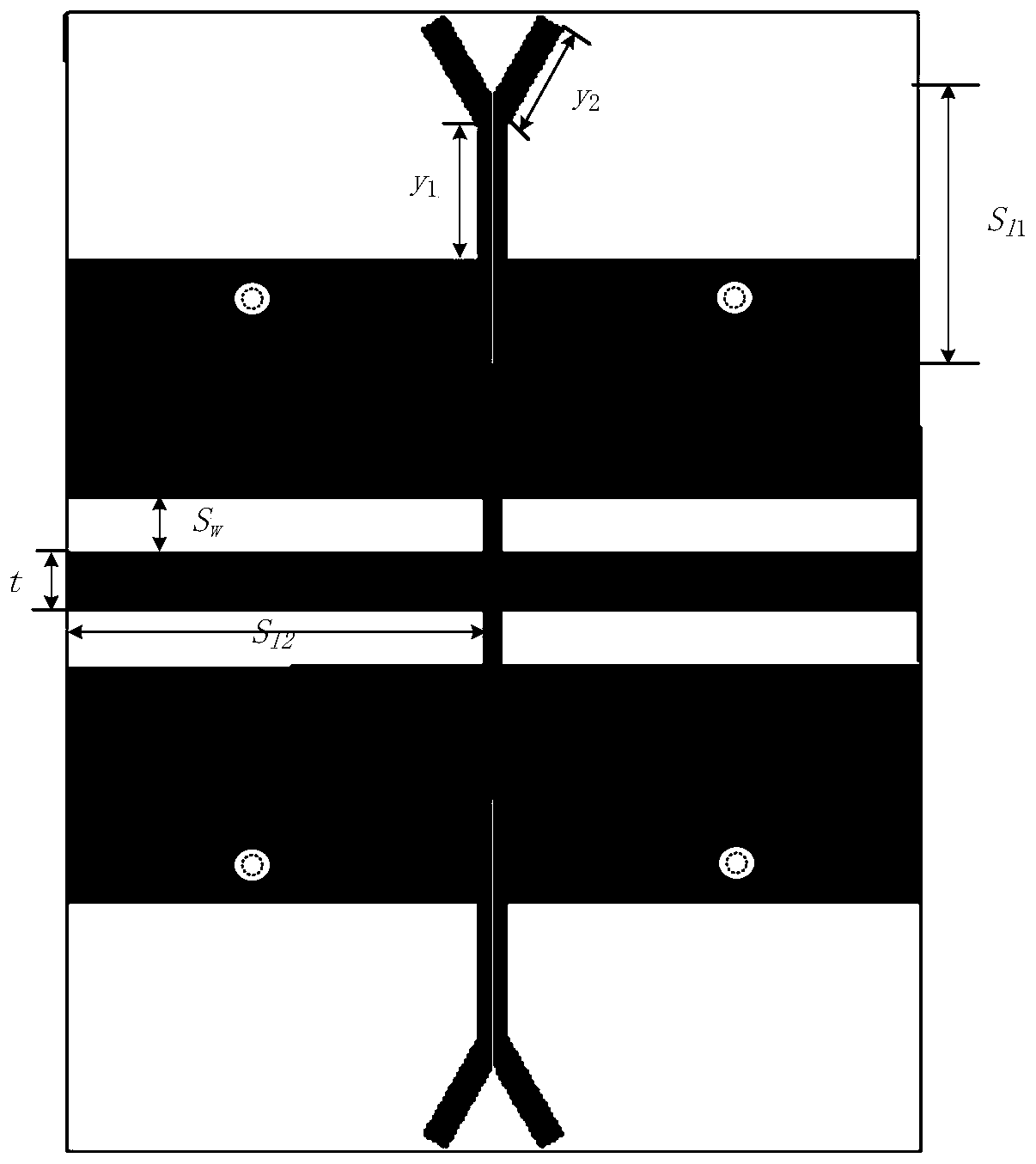
[0024] Such as figure 1 As shown, this embodiment provides a four-element MIMO antenna with small size, wide bandwidth, and high isolation. Its basic structure includes: a dielectric substrate, four antenna radiation elements, four microstrip feeders, a ground plate, four Rectangular floor slit, two middle slit Y-shaped branches. Wherein, the grounding plate is printed on the back of the dielectric board, and the grounding board is connected with the dielectric board in the form of a patch; the four antenna units are respectively placed at four corners of the front of the dielectric substrate, and placed back to back.

[0025] An example of the present invention is figure 1 As shown, as a preferred solution, the dielectric boar...


PUM


Abstract

The invention discloses a high-isolation three-frequency four-unit MIMO antenna. The high-isolation three-frequency four-unit MIMO antenna comprises a dielectric substrate, four antenna radiation units, four coaxial feeding head, a grounding plate, two intermediate slot Y-shaped branches and four rectangular floor gaps, wherein each antenna radiation unit employs a design of two antenna radiationsegment structures and comprises a first antenna radiation segment and a second antenna radiation segment, the first antenna radiation segment is in an inverted N-shaped bending line shape, the secondantenna radiation segment is in an L-shaped bending line shape, and the four antenna units are respectively placed at four corners of the dielectric substrate and are arranged in a back-to-back way.The working frequencies of the MIMO antenna are 2.5GHz, 3.5GHz and 5.8GHz, and the MIMO antenna can be applied to WLAN (2.4GHz and 5.8GHz) and 5G (3.5GHz) communication; moreover, the antenna has highisolation degree, and isolation degree exceeding 15dB is obtained among the antenna units within a frequency band higher than 2.4GHz; and the MIMO antenna is relatively small in integral size, wide in wideband and low in manufacturing cost and is simple to design, and mass production and processing are easy.

Description

technical field [0001] The invention relates to the technical field of antennas, in particular to a high-isolation three-frequency four-element MIMO antenna. Background technique [0002] With the rapid increase in the number of mobile users, consumers have an increasing demand for high-speed, high-quality signal transmission. The update and iteration of new technologies, new equipment, and new industries requires a large amount of spectrum resources. However, the non-renewability of spectrum resources prevents them from being overused. How to maximize the use of limited spectrum resources and fully explore space resources has become a hot topic of research by scholars at home and abroad. The proposal of the multiple-input multiple-output (Multiple-Input Multiple-Output, MIMO) technology makes it possible to solve the scarce spectrum resource and the increasing consumption demand. MIMO technology is to place multiple transmitting antennas and receiving antennas at the tran...

Claims


Application Information

Patent Timeline
Patent Type & Authority Applications(China)
IPC IPC(8): H01Q1/38H01Q1/48H01Q1/50H01Q1/52H01Q5/10H01Q5/28H01Q5/307H01Q21/00H01Q21/06
Inventor 金纯王腾黄琼
Owner CHONGQING UNIV OF POSTS & TELECOMM
Why Eureka
Try Eureka