
Rainproof distribution box

A technology of distribution box and box body, which is applied in substation/power distribution device casing, electrical components, substation/switch layout details, etc. It can solve problems such as leakage or power failure, safety accidents, poor waterproof performance, etc., and achieve cleanliness , Easy to operate, easy to change the effect

Inactive Publication Date: 2019-06-18
宁波永耀信息科技有限公司
View PDF1 Cites 2 Cited by
  • Summary
  • Abstract
  • Description
  • Claims
  • Application Information

AI Technical Summary

Problems solved by technology

However, the waterproof performance of this invention is relatively poor. Once the distribution box enters the water, it is easy to cause leakage or power failure. When the distribution box leaks electricity, it is easy to cause a safety accident.

Method used


Image

  • Rainproof distribution box
  • Rainproof distribution box
  • Rainproof distribution box

Examples


Embodiment 1

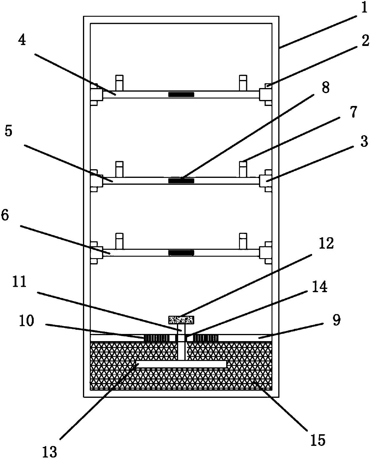
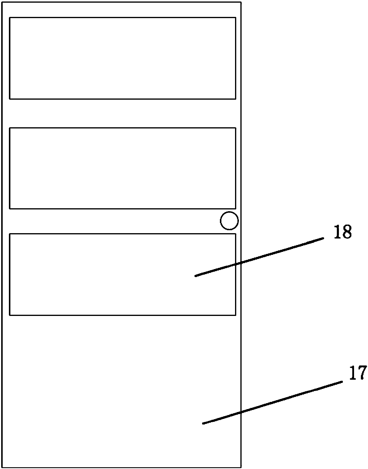
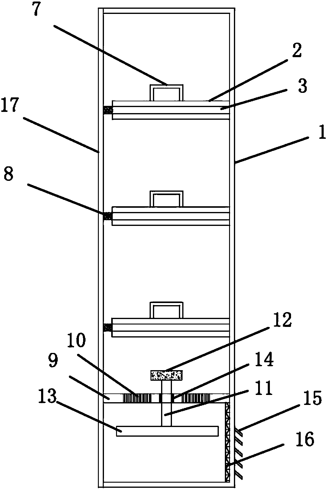
[0028] Such as figure 1 , figure 2 , image 3 As shown, the rainproof power distribution box includes a square box body 1 and a plugboard. The static contacts and chutes 2 of several electrical connectors are fixed in the box body 1. The moving contacts of the electrical connectors are installed on the plugboard. , the two sides of the board are coated with guide bars 3, the chute 2 is adapted to the guide bar 3 and fixed on the inner wall of the box body 1, the board includes an upper board 4, a middle board 5, a lower board On the board 6, the upper board 4 is equipped with a single-turn through-the-center transformer and an all-electronic multifunctional electric energy meter, the middle board 5 is equipped with a leakage circuit breaker and a modular surge protector, and the lower board 6 is equipped with a capacitor , miniature circuit breaker, capacitive switching contactor and reactive power compensation controller, in which the guide bar 3 not only makes the upper b...

Embodiment 2

[0034] This embodiment is substantially the same as the first embodiment, except that the material of the floating plate 13 is a PVC hollow plate. The material of the above-mentioned concentrated floating plate 13 is relatively light in weight. When the water level at the bottom of the distribution box rises, the floating plate 13 can be floated, so that the floating plate 13 can block the through holes on the ventilation partition 9 to prevent rainwater from entering the ventilation system. The upper layer of the partition 9.

Embodiment 3

[0036] This embodiment is substantially the same as the first embodiment, except that the material of the floating board 13 is EPS foam board. Foam boards are relatively inexpensive. And the buoyancy it receives under the same state will be relatively large.


PUM


Abstract

The invention provides a rainproof distribution box and belongs to the technical field of power distribution equipment. The rainproof distribution box comprises a square box body and plug-in boards, wherein the box body is fixed with static contacts and chutes of a plurality of electrical connectors, the plug-in boards are provided with movable contacts of the electrical connectors, both sides ofeach plug-in board are covered with guide strips, the chutes are adapted to the guide strips and fixed on the inner side wall of the box body, the plug-in boards comprise an upper plug-in board, a middle plug-in board and a lower plug-in board, the upper end surfaces of each plug-in board are fixed with two lifting handles, the outer ends of the plug-in boards are provided with pushing handles, aventilation partition is further horizontally arranged in the box body, the ventilation partition is located below the lower plug-in board, a plurality of ventilation holes are opened in the middle ofthe ventilation partition, the center of the ventilation partition is vertically disposed with a lifting rod, a supporting block is connected to the upper end of the lifting rod, a floating board isconnected to the lower end of the lifting rod, and the floating board completely blocks the ventilation holes after the lifting rod rises. The rainproof distribution box not only keeps the distribution box and the outside world with good ventilation, but also has good waterproofness and high safety.

Description

technical field [0001] The invention belongs to the technical field of power distribution equipment and relates to a rainproof power distribution box. Background technique [0002] Power distribution box is assembled in closed or semiclosed metal safe by electrical wiring requirement by switchgear, measuring instrument, protective device and auxiliary equipment or on screen width, forms low-voltage distribution equipment. During normal operation, the circuit can be connected or disconnected by means of a manual or automatic switch. Cut off the circuit or alarm with the help of protective electrical appliances in case of failure or abnormal operation. The distribution box is one of the most basic power supply facilities in urban construction. At present, the distribution box is mainly composed of a box body and internal components. However, the current distribution box is prone to overheating and short-circuit accidents after long-term use, and the current distribution box...

Claims


Application Information

Patent Timeline
Patent Type & Authority Applications(China)
IPC IPC(8): H02B1/46H02B1/28H02B1/56H02B1/48
Inventor 不公告发明人
Owner 宁波永耀信息科技有限公司
Learn More