
Backup power supply bus protection transformation system and method thereof for electric power system

A technology for busbar protection and backup power supply, applied in the direction of emergency protection circuit devices, electrical components, etc., can solve the problems of reducing the risk of 35kV system maintenance, poor flexibility, equipment aging, etc., and achieve the effect of reducing the scope of power outages and improving stability

Pending Publication Date: 2019-06-18
XIAN THERMAL POWER RES INST CO LTD
View PDF0 Cites 0 Cited by
  • Summary
  • Abstract
  • Description
  • Claims
  • Application Information

AI Technical Summary

Problems solved by technology

[0003] (1) High maintenance risk: two sections of busbar share a set of busbar protection device. When one section of busbar is out of service for maintenance, the other section of busbar and protection device continue to operate, resulting in increased maintenance risk and great impact on the safe and stable operation of the system. threaten;
[0004] (2) Poor flexibility: When the main body of the busbar protection device is overhauled, the two sections of 35kV busbars need to be shut down at the same time, which further reduces the reliability of the power supply of the system, and the maintenance flexibility of the protection device is poor;
[0005] (3) Equipment aging: the existing busbar protection has been put into operation for 12 years, and the electronic components of the microcomputer protection device have different degrees of unpredictable aging, which is not conducive to the safe and stable operation of the 35kV system
[0006] To sum up, the existing 35kV busbar protection is difficult to meet the reliability, safety and flexibility requirements of the current power system in terms of protection device performance and maintenance, reducing the maintenance risk of the 35kV system and affecting the backup power supply of the power plant. Continuous and stable operation of the system is of great significance

Method used


Image

  • Backup power supply bus protection transformation system and method thereof for electric power system
  • Backup power supply bus protection transformation system and method thereof for electric power system
  • Backup power supply bus protection transformation system and method thereof for electric power system

Examples


Embodiment Construction

[0058] The present invention will be further described in detail below in conjunction with specific embodiments, which are explanations of the present invention rather than limitations.

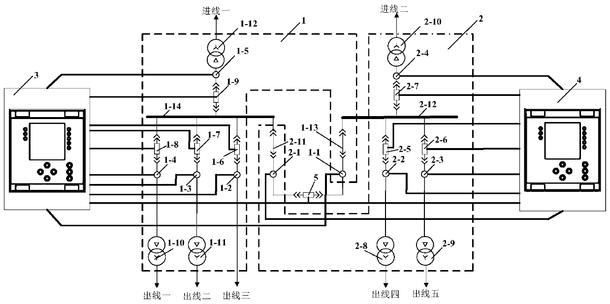
[0059] Such as figure 1 As shown, a power system backup power supply bus protection transformation system includes a first bus protection secondary circuit system 1, a second bus protection secondary circuit system 2, a first bus protection device 3, a second bus protection device 4 and a bus Connected section switch 5; wherein, the output and input ends of the first bus protection secondary circuit system 1 are connected to the first bus protection device 3 through cables, and the output and input ends of the second bus protection secondary circuit system 2 The input terminal is connected to the second busbar protection device 4 via a cable, and the position and signal control secondary circuit port of the busbar section switch 5 is connected to the first busbar protection device 3 and the s...


PUM


Abstract

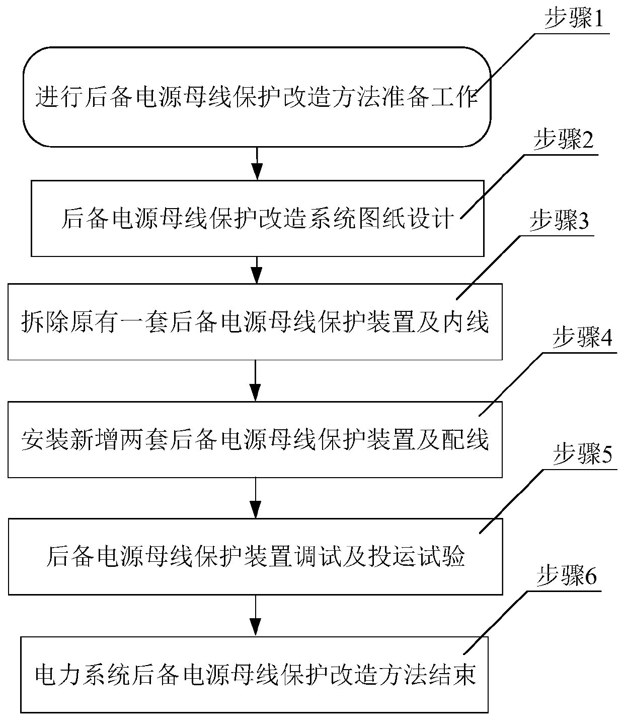
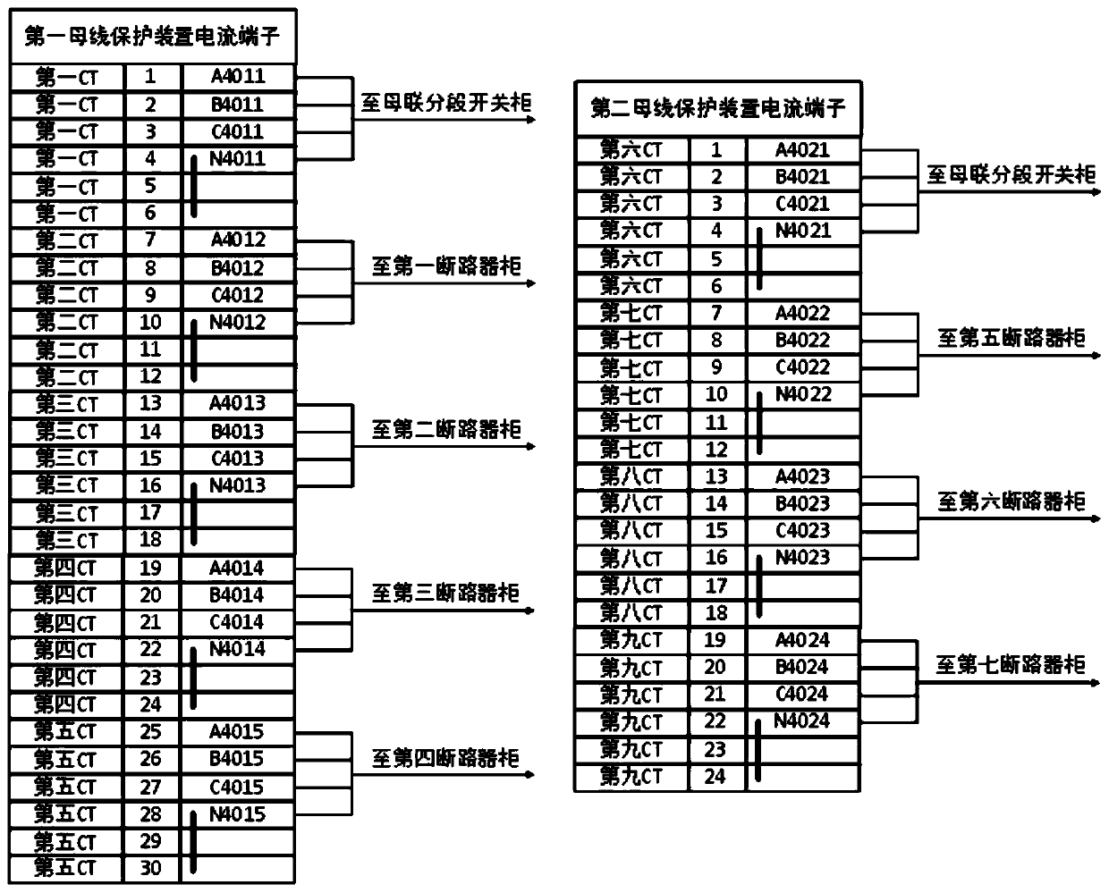
The invention relates to a backup power supply bus protection transformation system and a method thereof for an electric power system. The backup power supply bus protection transformation system comprises a bus protection current acquisition system I, a bus protection current acquisition system II, a bus protection device I, a bus protection device II and a bus connection section switch, whereinthe output end of the bus protection current acquisition system I is connected with the input end of the bus protection device I, and the output end of the bus protection current acquisition system IIis connected with the input end of the bus protection device II; the original bus protection device is transformed into two sets of bus protection devices through increasing buscouple CT current transformer, so that each section of bus is independently configured with one set of bus protection, the transformation keeps the wiring of the secondary circuit of the original protection screen unchanged, the original bus protection in the screen body is removed, and an additional bus protection device for the I and II section of the bus is installed. The two transformed section of bus protection isoperated independently and without mutual interference, which improves the system operation stability, further narrows the power failure range of the maintenance, and can improve the safety of the backup power supply bus protection system, and is convenient for inspection operation and has the advantage of flexibility.

Description

technical field [0001] The invention belongs to the technical field of backup power bus protection, and in particular relates to a power system backup power bus protection modification system and method. Background technique [0002] High-voltage busbar is an important part of power plant substation, and busbar fault is one of the most serious electrical faults. Conventional generator sets are connected to the booster station through the wiring of the generator-transformer unit. The backup power system of the whole plant is stepped down from the 500KV main system to 35kV through the step-down transformer, and then stepped down to 10KV or 6kV again through the standby transformer to supply the factory system. At present, the main wiring of the mainstream 35kV system is a single-bus section wiring mode, and a set of bus differential protection is set for the 35kV busbar system. The main problems of this type of configuration are as follows: [0003] (1) High maintenance risk...

Claims


Application Information

Patent Timeline
IPC IPC(8): H02H7/22
CPCY04S20/20Y02B70/30
Inventor 孙钢虎寇水潮王懂懂杨沛豪高峰冯仰敏
Owner XIAN THERMAL POWER RES INST CO LTD
Learn More