Power transmission real-time monitoring system

A real-time monitoring system, power transmission technology, applied in electrical components, frequency selection two-terminal pair network, angle modulation components and other directions, can solve problems such as affecting results, frequency hopping, etc.

Active Publication Date: 2019-06-18
内蒙古皖能建筑安装工程有限公司
View PDF5 Cites 10 Cited by
  • Summary
  • Abstract
  • Description
  • Claims
  • Application Information

AI Technical Summary

Problems solved by technology

The power industry provides a steady stream of electric energy for the development of the social economy. Its transmission lines, high-voltage towers, substations and other facilities all over the country are in daily operation. At present, the application of real-time monitoring system for power transmission has developed accordingly, which greatly saves It saves manpower and material resources and improves the efficiency of power energy detection. However, in pra

Method used


Image

  • Power transmission real-time monitoring system
  • Power transmission real-time monitoring system

Examples


Embodiment 1

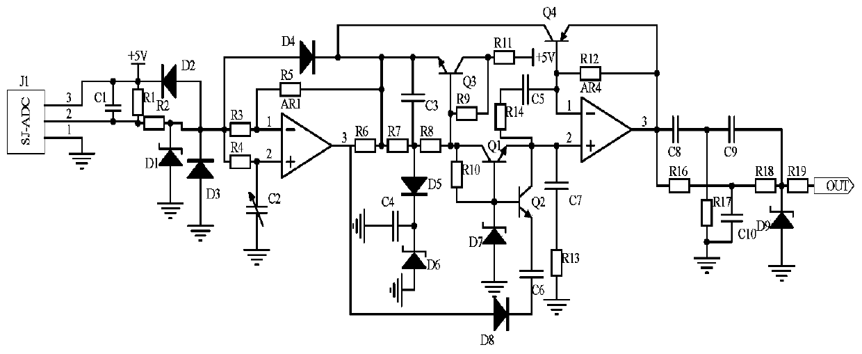
[0012] Embodiment 1, a power transmission real-time monitoring system, including a signal frequency acquisition circuit, a phase-shift feedback circuit and a frequency selection output circuit, the signal frequency acquisition circuit uses a signal frequency collector J1 model SJ-ADC to collect power transmission real-time In the monitoring system, the frequency of the data signal received by the control terminal is clamped by a clamp circuit composed of diode D2 and diode D3 to clamp the signal within 0 ~ +5V, and the phase shift feedback circuit uses operational amplifier AR1 and resistor R5 ~ resistor R8 And capacitor C3, capacitor C4 form a phase-shifting circuit to adjust the pulse width of the signal. At the same time, the transistor Q1 and the voltage regulator D7 are used to stabilize the voltage and then input to the same-phase input terminal of the operational amplifier AR4, and the transistor Q2 and capacitor C6 are used to feed back the signal to the base of the tran...

Embodiment 2

[0015] Embodiment 2. On the basis of Embodiment 1, the frequency selection output circuit uses resistors R16-resistor R18 and capacitor C8-capacitor C10 to form a frequency selection circuit to filter out a single frequency signal output, and the single frequency signal is relatively stable during transmission. That is to compensate the data signal potential received by the control terminal in the power transmission real-time monitoring system to prevent attenuation during data signal transmission. One end of the capacitor C8 is connected to the output end of the operational amplifier AR4 and one end of the resistor R16, and the capacitor C8 The other end is connected to one end of the capacitor C9 and one end of the resistor R17, the other end of the capacitor C9 is connected to the resistor R18, one end of the resistor R19 and the negative pole of the voltage regulator tube D9, the positive pole of the voltage regulator tube D9 is grounded, and the other end of the resistor R1...

Embodiment 3

[0016] Embodiment three, on the basis of embodiment one, the signal frequency acquisition circuit selects the signal frequency acquisition device J1 model SJ-ADC to collect the data signal frequency received by the control terminal in the power transmission real-time monitoring system, and uses diode D2, diode The clamp circuit composed of D3 clamps the signal within 0-+5V to prevent the signal potential from being too large to damage the circuit. At the same time, the regulator tube D1 stabilizes the voltage, and the power supply terminal of the signal frequency collector J1 is connected to capacitor C1, one end of resistor R1 and Power supply +5V and the negative pole of diode D2, the ground terminal of signal frequency collector J1 is grounded, the output terminal of signal frequency collector J1 is connected to capacitor C1, the other end of resistor R1 and one end of resistor R2, and the other end of resistor R2 is connected to the regulator The cathode of the tube D1 and ...


PUM


Abstract

The invention discloses a power transmission real-time monitoring system, which comprises a signal frequency acquisition circuit, a phase shift feedback circuit and a frequency selection output circuit, and is characterized in that the signal frequency acquisition circuit adopts an SJ-type; A signal frequency collector J1 of the ADC collects the frequency of a data signal received by a control terminal in the power transmission real-time monitoring system. The phase shift feedback circuit uses an operational amplifier AR1, resistors R5 to R8 and a capacitor C3. the capacitor C4 forms a phase shift circuit to adjust the signal pulse width; A triode Q1 and a voltage-regulator tube D7 are used for voltage stabilization and then input into the in-phase input end of an operational amplifier AR4, a triode Q2 and a capacitor C6 are used for feeding back signals to the base electrode of a triode Q3, a triode Q4 is used for feeding back signals to the emitting electrode of the triode Q3. Finally, the frequency selective output circuit uses a resistor R16-resistor R18 and a capacitor C8-capacitor C10 to form a frequency selective circuit to screen out a single frequency signal output., so that the frequency of a data signal received by a control terminal in the power transmission real-time monitoring system can be monitored in real time, and signal frequency modulation and voltage stabilization are carried out.

Description

technical field [0001] The invention relates to the field of circuit technology, in particular to a power transmission real-time monitoring system. Background technique [0002] With the rapid development of my country's national economy, the demand for energy from all walks of life is also increasing, and for the power industry that provides the main energy for the society, its social responsibility is also becoming more and more important. The power industry provides a steady stream of electric energy for the development of the social economy. Its transmission lines, high-voltage towers, substations and other facilities all over the country are in daily operation. At present, the application of real-time monitoring system for power transmission has developed accordingly, which greatly saves It saves manpower and material resources and improves the efficiency of power energy detection. However, in practice, due to the variety of environments in the power transmission proces...

Claims


Application Information

Patent Timeline
IPC IPC(8): H03C3/02H03D7/00H03H11/04
Inventor 张帆胡佳
Owner 内蒙古皖能建筑安装工程有限公司
Why Eureka
Try Eureka