
Narrow-band tunable filter with a low frequency band

A low-pass filter and filter technology, applied in impedance networks, electrical components, multi-terminal-pair networks, etc., can solve problems such as system accuracy decline, widening bandwidth, and signal-to-noise ratio reduction.

Active Publication Date: 2019-06-18
UNIV OF ELECTRONICS SCI & TECH OF CHINA
View PDF5 Cites 2 Cited by
  • Summary
  • Abstract
  • Description
  • Claims
  • Application Information

AI Technical Summary

Problems solved by technology

On the basis of high precision, the widest possible system bandwidth is required. However, the main problem faced by traditional filters is that the signal-to-noise ratio of the signal will decrease with the widening of the system bandwidth. Directly enlarging the bandwidth will lead to the loss of the entire system. Accuracy drops
In fact, under narrow-band conditions, the accuracy can already meet the requirements, so how to achieve high-precision acquisition of filters under wide-band conditions has become a problem that must be considered to improve system performance

Method used


Image

  • Narrow-band tunable filter with a low frequency band
  • Narrow-band tunable filter with a low frequency band
  • Narrow-band tunable filter with a low frequency band

Examples


Embodiment 1

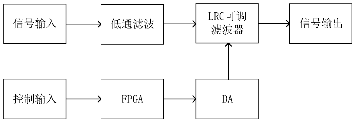
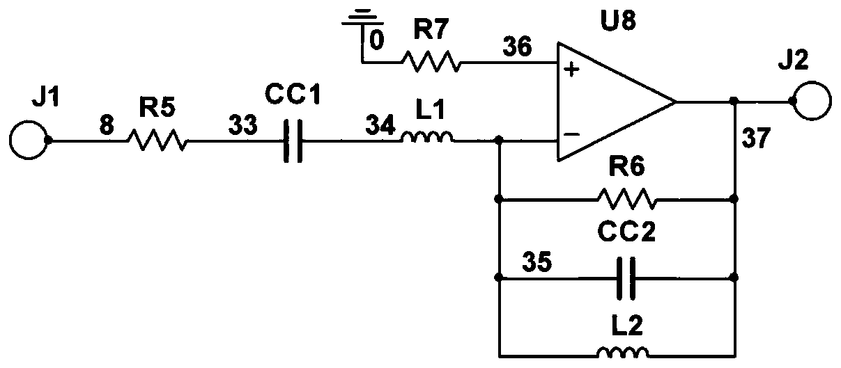
[0061] In this example, the frequency adjustment upper limit f of the LRC narrowband tunable filter max Is defined as 100KHz, frequency adjustment lower limit f min It is defined as 36.25KHz, the speed of FPGA scanning user control port P1 is set to 100Hz, the values ​​of filter inductors L1 and L2 are L=25mH, and the corresponding adjustment range of voltage-controlled capacitors CC1 and CC2 is 100pF~771pF,

[0062] The program of the programmable gate array FPGA is as follows: After power-on, the self-test of the device and the initialization of the digital-to-analog converter DAC are completed. , Resistor R5-R7) The center frequency is placed at f max =100KHz, after that, the FPGA scans the user control port P1 circularly at a frequency of 100Hz to detect whether there is a control signal incoming. The control signal is defined by the filter designer. For example, an 8-bit length control code is used in this design (can represent 0~ 255, a total of 256 cases), defined 256...


PUM


Abstract

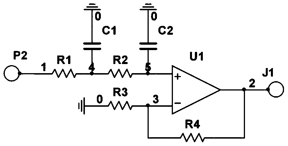
The invention relates to a narrow-band tunable filter with a low frequency band, which solves the problem that the filtering frequency band of a low-frequency signal is difficult to adjust in the traditional filter circuit design. The voltage-controlled capacitor chip is adopted to replace a traditional variable-capacitance diode method, so that the problem of waveform distortion caused by superposition of a variable-capacitance diode control channel and a signal channel is solved. And meanwhile, the LRC filter circuit is improved and combined, so that the problem of low quality factor of thetraditional RC filter circuit is solved. The filter has the advantages of being narrow in frequency band, high in quality factor, small in signal deformation after filtering and the like, the adjustable range of the frequency band is further widened by means of the parallel connection design of the capacitors, and the filter can be widely applied to noise filtering of a low-frequency harmonic circuit and a high-precision acquisition circuit.

Description

technical field [0001] The invention relates to the field of data acquisition, in particular to an analog signal filtering system in data acquisition. Background technique [0002] With the development of electronic power technology and large-scale integration technology, the information processing system has higher and higher requirements on the performance of the data acquisition system. On the basis of high precision, the widest possible system bandwidth is required. However, the main problem faced by traditional filters is that the signal-to-noise ratio of the signal will decrease with the widening of the system bandwidth. Directly enlarging the bandwidth will lead to the loss of the entire system. Accuracy drops. In fact, under narrow-band conditions, the accuracy can already meet the requirements, so how to achieve high-precision acquisition of filters under wide-band conditions has become a problem that must be considered to improve system performance. Contents of ...

Claims


Application Information

Patent Timeline
Patent Type & Authority Applications(China)
IPC IPC(8): H03H7/01H03H1/02
Inventor 张治国王艺璇施博文赖小松
Owner UNIV OF ELECTRONICS SCI & TECH OF CHINA
Learn More