Clamp for ultrasonic welding machine

An ultrasonic and fixture technology, applied in the ultrasonic field, can solve the problems of unable to maintain the leveling state, take a lot of time, affect the automatic production rhythm and product quality, and achieve the effect of improving the working rhythm, improving the welding quality, and complete functions

Inactive Publication Date: 2019-06-21
SBT ULTRASONIC TECH CO LTD
View PDF7 Cites 6 Cited by
  • Summary
  • Abstract
  • Description
  • Claims
  • Application Information

AI Technical Summary

Problems solved by technology

The welding head and the machine base are flipped together as a whole, and the working surface of the welding head will not be able to maintain the pre-leveled state. The staff spend a lot of time repeatedly fine-tuning, which affects the automatic production cycle and product quality

Method used


Image

  • Clamp for ultrasonic welding machine
  • Clamp for ultrasonic welding machine
  • Clamp for ultrasonic welding machine

Examples


Embodiment 1

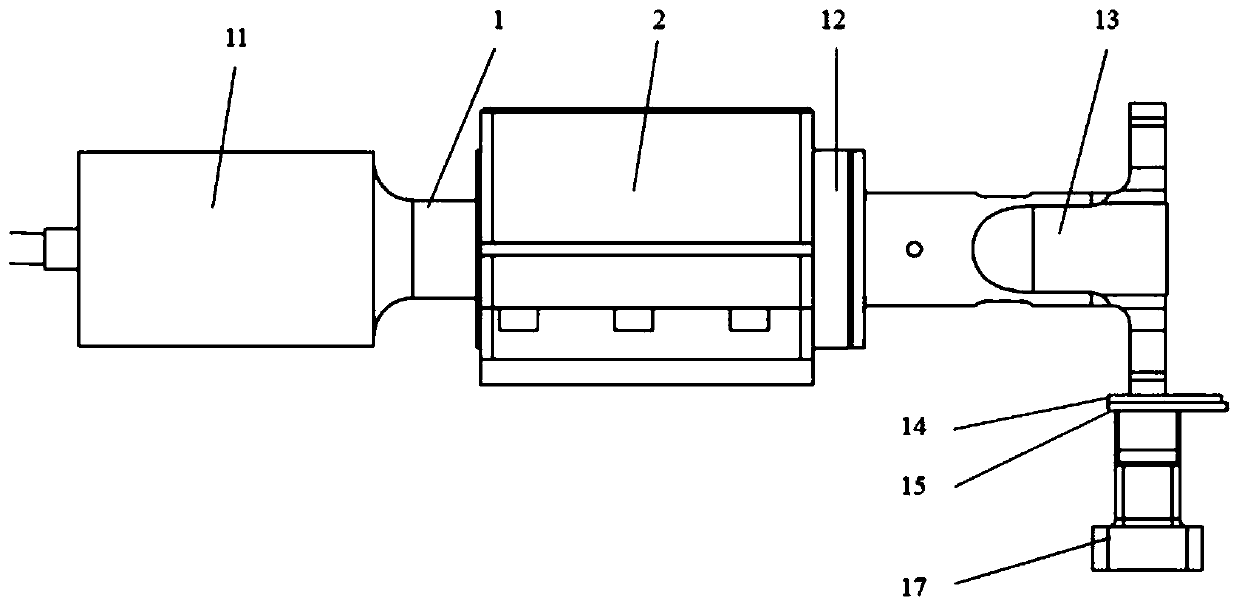
[0015] Such as figure 1 As shown, this specific embodiment adopts the following technical solutions: a fixture for an ultrasonic welder, including: a weldment 15, and also includes a triplet 1, a fixture 2, a transducer 11, an amplitude modulator 12, a welding head 13, The welding area 14 and the anvil 17; the right side of the transducer 11 is connected with a triplet 1; the right side of the triplet 1 is connected with an amplitude modulator 12; the right side of the amplitude modulator 12 is connected with a Welding head 13; the lower end of the welding head 13 is provided with a welding area 14; the welding piece 15 is arranged on the anvil 17; the welding area 14 is in contact with the welding piece 15; the clamp 2 is arranged in a triple group 1 on the outer surface.

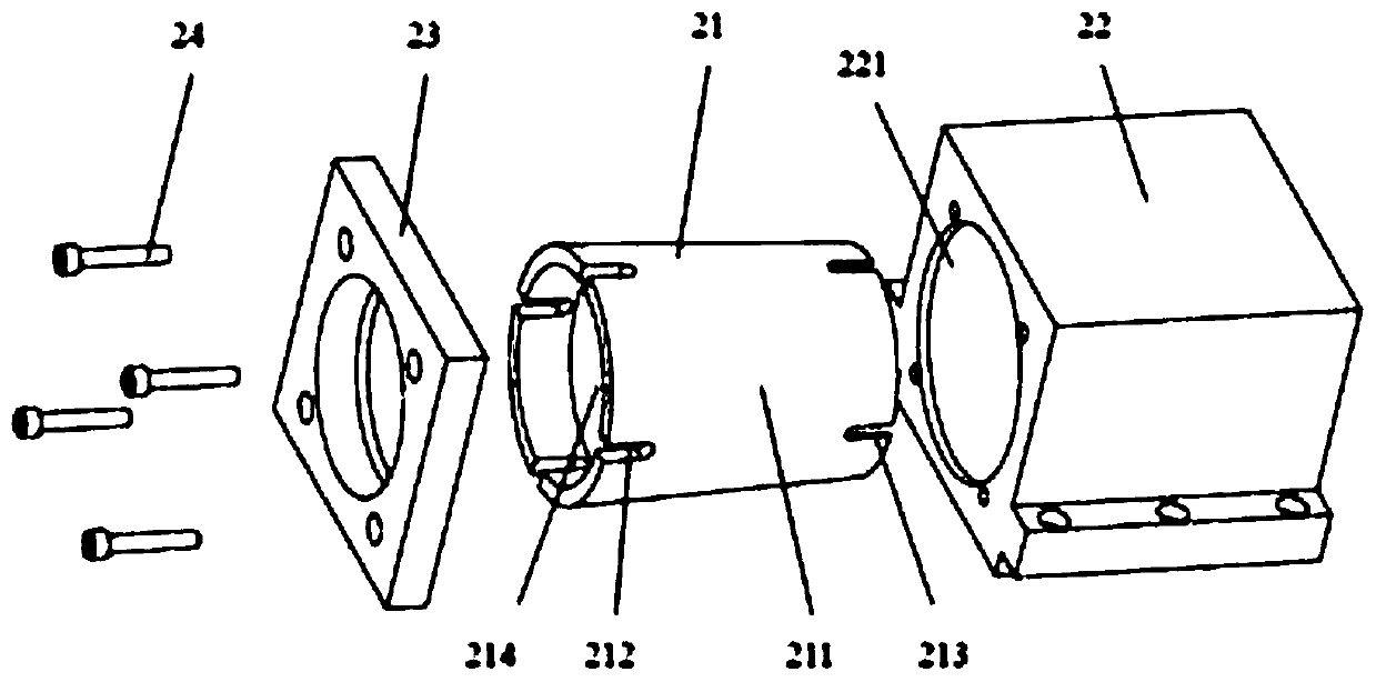
[0016] Such as figure 2 As shown, the specific structure of the clamp 2 is: comprising a first bushing 21, a first frame 22, a first cover plate 23 and a first screw 24; the first bushing 21 is arranged...

Embodiment 2

[0019] Such as figure 1 As shown, this specific embodiment adopts the following technical solutions: a fixture for an ultrasonic welder, including: a weldment 15, and also includes a triplet 1, a fixture 2, a transducer 11, an amplitude modulator 12, a welding head 13, The welding area 14 and the anvil 17; the right side of the transducer 11 is connected with a triplet 1; the right side of the triplet 1 is connected with an amplitude modulator 12; the right side of the amplitude modulator 12 is connected with a Welding head 13; the lower end of the welding head 13 is provided with a welding area 14; the welding piece 15 is arranged on the anvil 17; the welding area 14 is in contact with the welding piece 15; the clamp 2 is arranged in a triple group 1 on the outer surface.

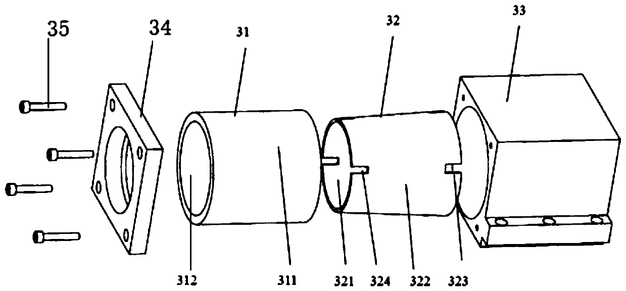
[0020] Such as image 3 As shown, the specific structure of the clamp 2 is: including a second bushing 31, a third bushing 32, a second base 33, a second cover plate 34 and a second screw 35; the second ...


PUM


Abstract

The invention discloses a clamp for an ultrasonic welding machine. The clamp is reasonable and simple in structure, low in production cost, convenient to install and complete in function, and can realize rapid positioning and clamping of a welding triplicate assembly, and effectively improve the welding quality and the working efficiency. The clamp comprises a machine base, a bush and an end cover, wherein the machine base is fixed to a workbench of the welding machine, the bush is arranged at an inner ring of the machine base and provided with a groove, and the end cover is provided with a fixing screw hole and exerts clamping force. The bush is embedded into the machine base, the ultrasonic welding triplicate assembly is placed inwards, and ultrasonic triplicate leveling is completed. When the end cover is fixed to the machine base, the bush deforms in the machine base, so that the triplicate assembly can be stably clamped, the leveling state of the triplicate assembly is kept, and the purposes of fast positioning and clamping of the triplicate assembly are realized.

Description

technical field [0001] The invention relates to the field of ultrasonic technology, in particular to a fixture for an ultrasonic welding machine. Background technique [0002] The parallel state of the surface of the welding head in the triple assembly of the ultrasonic welding machine and the welding working surface is an important factor for the quality of ultrasonic welding and the life of the welding head. At present, the ultrasonic welding machine generally clamps and fixes the triplet of the ultrasonic welding machine through a C-shaped machine base with slots on the side. In the process of clamping the three-unit machine base with this kind of clamp, the side of the outer surface of the cylinder will produce a small displacement in the circumferential direction under the action of friction force. If the welding head and machine base are flipped together as a whole, the working surface of the welding head will not be able to maintain the pre-leveled state, and the sta...

Claims


Application Information

Patent Timeline
Patent Type & Authority Applications(China)
IPC IPC(8): B23K20/10B23K20/26B23K37/04
Inventor 周宏建孙稳石新华
Owner SBT ULTRASONIC TECH CO LTD
Why Eureka
Try Eureka