Steel wire rope intelligent hoisting and lifting device

A steel wire rope and intelligent technology, applied in the field of steel wire rope intelligent hoisting and lifting equipment, can solve the problems of poor impact resistance of servo motors, center of gravity not in the middle of the lifting rope, slip rings are prone to problems, etc., achieve good weighing effect and reduce equipment length Small size, good appearance and image effect

Inactive Publication Date: 2019-06-21
袁匡柳
View PDF6 Cites 4 Cited by
  • Summary
  • Abstract
  • Description
  • Claims
  • Application Information

AI Technical Summary

Problems solved by technology

[0003] 1. In order for the steel wire rope to run out of the chute, the steel wire rope on the winding disc of the main engine is tightly held by reinforced nylon and metal parts. The nylon parts will be worn off by the steel wire rope within half a year of equipment operation, and then the steel wire rope will grind the metal parts, causing the steel wire rope to be worn out. , so the wire rope needs to be replaced frequently;
[0004] 2. The main machine basically adopts the servo motor imported from abroad. The servo motor is mainly used for precision control, and the torque is only one-fifth of that of other motors with the same volume. The product with high capacity is too large in size, and the center of gravity is not in the middle of the lifting rope. At the same time, the servo motor has poor impact resistance. It will alarm when overloaded. a lot of working hours;
[0005] 3. The slip ring of the handle part is prone to problems

Method used


Image

  • Steel wire rope intelligent hoisting and lifting device
  • Steel wire rope intelligent hoisting and lifting device
  • Steel wire rope intelligent hoisting and lifting device

Examples


Embodiment Construction

[0038] The present invention will be described in detail below in conjunction with specific embodiments. The following examples will help those skilled in the art to further understand the present invention, but do not limit the present invention in any form. It should be noted that those skilled in the art can make several modifications and improvements without departing from the concept of the present invention. These all belong to the protection scope of the present invention.

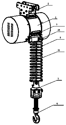
[0039] Such as Figure 1-Figure 13 As shown, the embodiment of the present invention provides a kind of steel wire rope intelligent hoisting and lifting equipment, comprising a host 1, an I-shaped trolley 2 installed on the top surface of the host 1, a spring 3 installed on the lower bottom of the host, and a spring clamp 4 installed The handle 5 at the lower end of the spring 3, the rotating hook assembly 6 installed at the lower end of the handle 5, and the proximity sensor 7 installed on the lo...


PUM


Abstract

The invention discloses a steel wire rope intelligent hoisting and lifting device comprising a main machine, an I-shaped trolley mounted on the top surface of the main machine, a spring mounted on thelower bottom surface of the main machine, a handle mounted at the lower end of the spring through a spring clip, a rotating hook assembly installed at the lower end of the handle and a proximity sensor mounted on the lower side face of the main machine; a steel wire rope in the main machine extends out from an opening below the main machine to penetrate the spring to be fixedly connected with theupper end of the handle; the main machine includes a front cover and a rear cover, the rear cover is internally provided with a first stepping motor and a steel wire rope winding disc, the steel wirerope winding disc is connected to the outside of the first stepping motor in a sleeving manner through a rolling bearing, the driving end of the first stepping motor is connected to the steel wire rope winding disc through a planetary reducer so as to be used for driving the steel wire rope winding disc to rotate, and the front cover is internally provided with a 103v electromagnetic brake pad matched with the driving end of the first stepping motor. The equipment and accessories of the steel wire rope intelligent hoisting and lifting device are all made in China, the cost is reduced, the body shape becomes small, the center of gravity is in the middle portion and is not inclined, and the steel wire rope is not prone to being abraded.

Description

technical field [0001] The invention relates to the field of small lifting devices, in particular to a steel wire rope intelligent lifting equipment. Background technique [0002] At present, the existing domestic wire rope hoisting equipment generally has the following defects: [0003] 1. In order for the steel wire rope to run out of the chute, the steel wire rope on the winding disc of the main engine is tightly held by reinforced nylon and metal parts. The nylon parts will be worn off by the steel wire rope within half a year of equipment operation, and then the steel wire rope will grind the metal parts, causing the steel wire rope to be worn out. , so the wire rope needs to be replaced frequently; [0004] 2. The main machine basically adopts the servo motor imported from abroad. The servo motor is mainly used for precision control, and the torque is only one-fifth of that of other motors with the same volume. The product with high capacity is too large in size, and...

Claims


Application Information

Patent Timeline
Patent Type & Authority Applications(China)
IPC IPC(8): B66D1/12B66D1/28B66D5/30H02K37/24
Inventor 袁匡柳
Owner 袁匡柳
Why Eureka
Try Eureka