
Method for determining tool face angle in three-dimensional borehole trajectory control

A technology of tool face angle and wellbore trajectory, which is applied in wellbore/well components, directional drilling, earthwork drilling and production, etc., can solve the problems of lower drilling efficiency, failure to hit the target, and long time consumption, so as to improve drilling efficiency and save The effect of daily drilling cost and strong operability

Active Publication Date: 2019-06-21
PETROLEUM ENG TECH RES INST CHINA PETROLEUM & CHEM CORP NORTH CHINA OIL & GAS CO +1
View PDF5 Cites 6 Cited by
  • Summary
  • Abstract
  • Description
  • Claims
  • Application Information

AI Technical Summary

Problems solved by technology

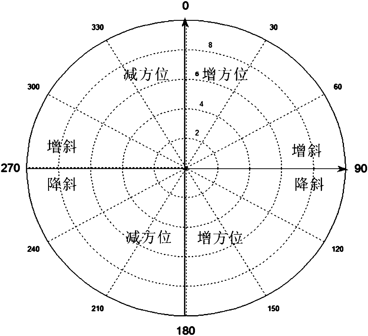
In the orientation process of two-dimensional directional wells and horizontal wells, the tool face angle (some are called device angles) is either 0° or 180°, which is relatively simple to determine; while three-dimensional directional wells and horizontal wells not only change the well deviation, but also the azimuth It is also constantly changing. The determination of the tool face angle is a very important parameter. If the on-site orientation is not determined properly, it will be "missed by a tiny bit, and it will be a thousand miles away".
In the conventional orientation of "screw drilling tool + MWD", the determination of the tool face angle on site involves many factors. At present, it mainly relies on the experience of drillers and directional engineers, supplemented by theoretical calculations. The tool face angle is constantly adjusted, trial and error, It takes a long time, the probability of complex situations at the bottom of the well will increase, and at the same time, the drilling efficiency will be reduced and the cost will be increased

Method used


Image

  • Method for determining tool face angle in three-dimensional borehole trajectory control
  • Method for determining tool face angle in three-dimensional borehole trajectory control
  • Method for determining tool face angle in three-dimensional borehole trajectory control

Examples


Embodiment 1

[0023] Taking a 3D horizontal well in Jinghe Oilfield, Ordos Basin as an example, this example is to control the wellbore trajectory by drilling a string of drill pipe in the 3D directional well section. The specific steps of the method for determining the tool face angle in the three-dimensional wellbore trajectory control in this embodiment are as follows:

[0024] (1) In the initial section of the 3D directional well, the actual build-up rate of the drill tool assembly is determined according to the deflection measurement data of the 2D directional section. The drilling tool assembly of this well section is shown in Table 1:

[0025] Table 1. Relevant values ​​of 2D directional drilling tools

[0026] name steel grade Inner diameter×outer diameter(mm) Buckle type Quantity (root) length (m) 8 1 / 2 "Teeth wheel

dedicated 215.9 431 1 0.33 1.5° screw special material 35×172 430×410 1 8.30 non-magnetic special material 72...

Embodiment 2

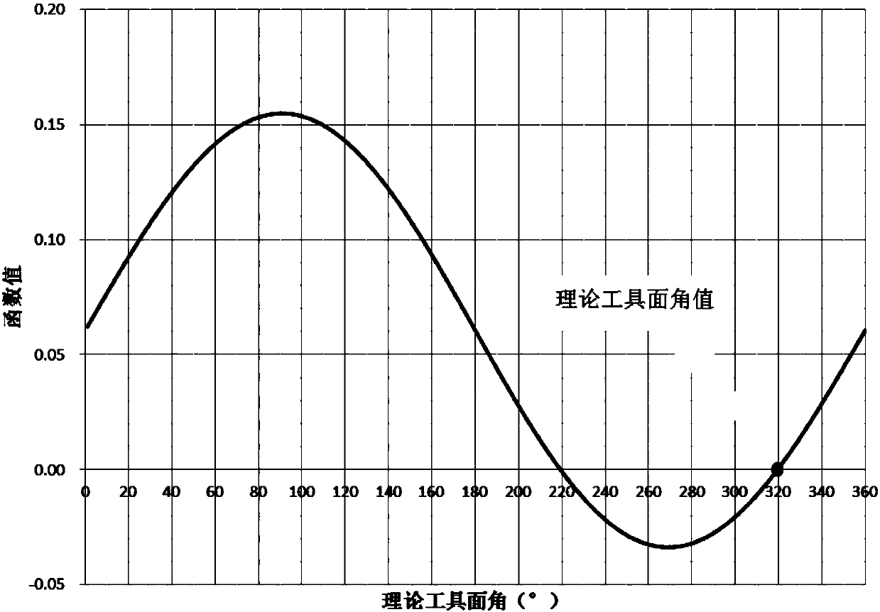
[0046] The specific steps of the method for determining the tool face angle in the three-dimensional wellbore trajectory control in this embodiment are as follows:

[0047] (1) For a three-dimensional horizontal well, the build-up rate of the drilling tool assembly is 3.75° / 30m. In the three-dimensional directional well section, it is drilled to 1414.74m, ready for the next string of drill pipe construction.

[0048] (2) Determine the numerical values ​​used in Formula I.

[0049] A. According to the MWD inclination measurement data, after calculation, the bottom hole inclination angle is α 1 =59.45°, the well inclination azimuth is Φ 1 =15.60°, actual drilling vertical depth is D 1 =1321.47m;

[0050] B. After measurement, the length of the drill pipe to be lowered is ΔL=27.18m (generally composed of 3 single pieces);

[0051] C. The vertical depth D of the point to be drilled 2 =1334.97m, the azimuth angle of well inclination is twisted to Φ 2 =12.80°;

[0052] D. On-si...


PUM


Abstract

The invention relates to a method for determining a tool face angle in three-dimensional borehole trajectory control, and belongs to the technical field of petroleum and gas drilling. According to themethod for determining the tool face angle in the three-dimensional borehole trajectory control, a well bottom hole deviation angle and a well deviation azimuth angle are measured, and the well bottom actual drilling vertical depth is calculated; the length of a to-be-lowered drill stem is measured; the vertical depth and the well deviation azimuth angle of a to-be-drilled point are determined; in a three-dimensional directional well section, under stable bit pressure and displacement, a reverse torsion angle value is measured; the difference between the to-be-drilled point vertical depth andthe bottom hole actual drilling vertical depth is calculated, and finally an actual tool face angle is obtained through a formula I. The problem of determining the tool face angle in three-dimensional well orientation is solved, the numerical value is accurate, high operability is achieved, support is provided for an on-site orientation engineer and a driller, the drilling efficiency is improved,the daily cost of drilling is reduced, and conditions are created for smooth construction.

Description

technical field [0001] The invention relates to a method for determining a tool face angle in three-dimensional wellbore trajectory control, and belongs to the technical field of oil and gas drilling. Background technique [0002] In the field of oil and gas technology, in order to improve the reserve production rate of reservoirs, increase single well production, and reduce engineering costs, horizontal wells are used for production capacity construction, and good implementation results have been achieved. However, in the process of horizontal well development, the well site layout is difficult. For example, there are many ravines on the surface, and there are many "plateaus, beams, and hills"; there are many rivers, roads, and forestry; and the density of drilled wells is relatively high. Therefore, since the original two-dimensional directional wells and horizontal wells cannot meet the requirements, three-dimensional directional wells and horizontal wells are particularl...

Claims


Application Information

Patent Timeline
Patent Type & Authority Applications(China)
IPC IPC(8): E21B7/04E21B47/022G06Q50/02
Inventor 李建山王翔闫吉曾赵文彬张永清
Owner PETROLEUM ENG TECH RES INST CHINA PETROLEUM & CHEM CORP NORTH CHINA OIL & GAS CO
Learn More