
Near field probe range finding method and device based on laser reflection

A technology of laser reflection and ranging method, which is applied in the field of terahertz microscopic imaging, can solve the problem of accurately measuring the distance between the photoconductive microprobe and the sample that has not yet been proposed

Inactive Publication Date: 2019-06-21
CHONGQING INST OF GREEN & INTELLIGENT TECH CHINESE ACADEMY OF SCI
View PDF0 Cites 2 Cited by
  • Summary
  • Abstract
  • Description
  • Claims
  • Application Information

AI Technical Summary

Problems solved by technology

However, for a long time, people have only been using CCD to obtain images and judge the approximate distance with the naked eye and experience, and have not yet proposed a method for accurately measuring the distance between the photoconductive microprobe and the sample and automatically adjusting the distance

Method used


Image

  • Near field probe range finding method and device based on laser reflection
  • Near field probe range finding method and device based on laser reflection
  • Near field probe range finding method and device based on laser reflection

Examples


Embodiment 1

[0034] Embodiment 1: Measuring the distance between the photoconductive microprobe and the sample

[0035] Step 1: Image acquisition and processing

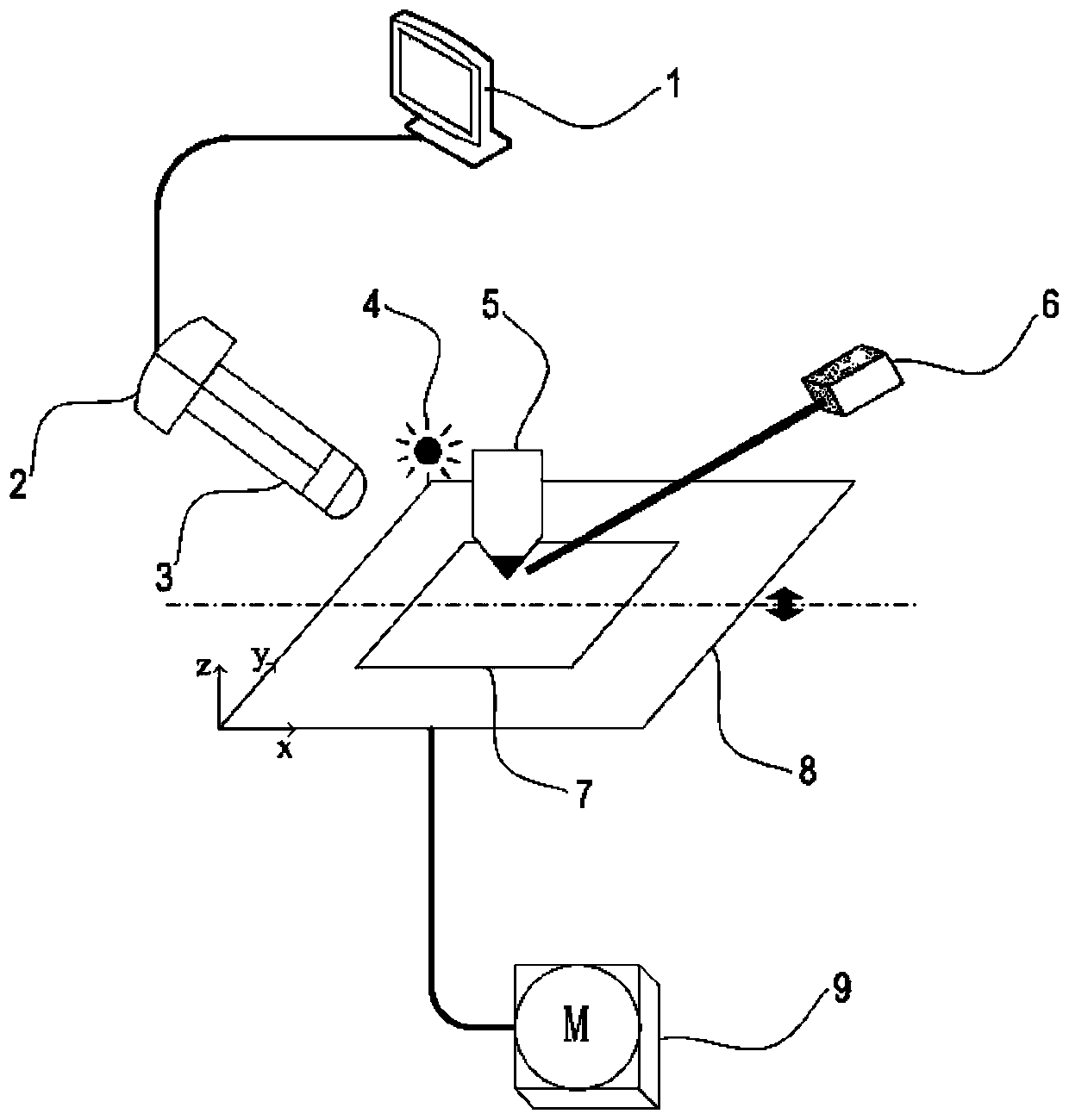
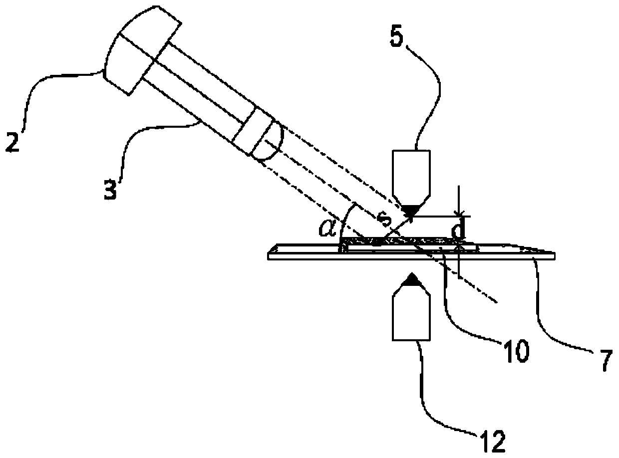
[0036] After adjusting the instrument and equipment, run the terahertz near-field scanning system to control the motor control box to move the sample toward the tip of the photoconductive microprobe (all sample movement operations in this system must be based on the fact that the sample does not touch the photoconductive microprobe. principle), after seeing the mirror image of the needle tip or the laser spot on the sample on the image fed back by the CCD, select a small amount of micron-level stepping movement, and then collect the color image transmitted by the CCD on the computer, and perform image processing and features on the collected image Extraction and other methods to obtain the photoconductive microprobe-sample spacing S on the image 1 .

[0037] Step 2: The measured image and the actual scale k

[0038] Control th...

Embodiment 2

[0041] Example 2: Automatically adjust and measure the distance between the photoconductive microprobe and the sample

[0042] Step 1: Image acquisition and scale determination

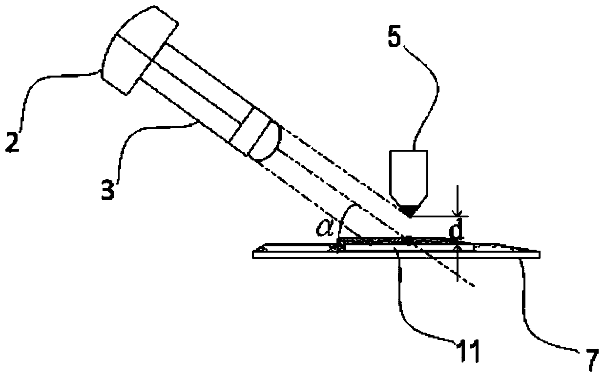
[0043] With step one, two in embodiment 1, measure scale k (wherein, for the sample with smooth surface, its image and actual scale are k 1 , for a sample with a rough surface, its image and actual scale bar is k 2 ).

[0044] Step 2: Automatically adjust the spacing system

[0045] Preset probe-sample spacing safety value d 0 , during the sample scanning test process, real-time extraction of the distance S on the image by computer, calculate the actual distance d according to the corresponding scale, and compare d with d 0 The size relationship is transmitted to the system control center, and then the movement of the sample in the Z direction is adjusted through the communication between the control center and the sample stage. Therefore, during the terahertz near-field scanning test, the distan...


PUM


Abstract

The invention relates to a near field probe range finding method and device based on laser reflection and belongs to the terahertz microscopic imaging field. The method is realized based on the near field probe range finding device. The range finding device comprises a laser, a visible light source, a visible light microscope, a photoconductive microprobe, a sample, a sample displacement bench, amotor control box, and a computer. The method comprises the following steps of S1, placing the sample on the sample displacement bench; S2, irradiating visible light on a tip of the photoconductive microprobe, and acquiring a scene near the tip in real time through the visible light microscope and a CCD detector, and transmitting to the computer for image processing and characteristic extraction,and obtaining a spacing S of the photoconductive microprobe-sample on an image scale; and S3, calculating and acquiring an actual distance d of the photoconductive microprobe-sample through a relational expression between the spacing S on the image scale and an actual spacing. The method and the device are used for accurately measuring the spacing between the photoconductive microprobe and the sample and automatically adjusting the spacing.

Description

technical field [0001] The invention belongs to the field of terahertz microscopic imaging, and relates to a laser reflection-based near-field probe ranging method and device. Background technique [0002] In recent years, terahertz (THz) technology has become a research hotspot at home and abroad. According to the Rayleigh criterion, the traditional THz far-field imaging system is limited by the diffraction limit, and the highest spatial resolution of imaging can only reach half of the wavelength (1 THz corresponds to a wavelength of 300 μm). Using THz near-field scanning imaging technology, the spatial resolution of imaging can break through the diffraction limit, reach sub-wavelength dimensions, and even reach nanoscale. [0003] The THz near-field scanning imaging system based on photoconductive microprobes can achieve micron-level resolution imaging detection in the terahertz band, and has been used in functional device detection, biological tissue imaging, and materia...

Claims


Application Information

Patent Timeline
Patent Type & Authority Applications(China)
IPC IPC(8): G01S17/08
CPCG01S17/08
Inventor 王化斌郭缘森李早霞耿国帅杨忠波
Owner CHONGQING INST OF GREEN & INTELLIGENT TECH CHINESE ACADEMY OF SCI
Learn More