Universal solar control system

A control system and solar energy technology, applied in the field of general-purpose solar energy control systems, can solve the problems of high cost, unfavorable market promotion and popularization, unfavorable market promotion and popularization, waste of electric energy, etc. Stream IC circuit, avoid flashing lights, reduce system cost

Inactive Publication Date: 2019-06-21
中山市核芯动力电子科技有限公司
View PDF0 Cites 1 Cited by
  • Summary
  • Abstract
  • Description
  • Claims
  • Application Information

AI Technical Summary

Problems solved by technology

[0002] Lithium battery solar lighting control systems currently on the market are developed for different battery voltages, and adopt step-down and current-limiting methods. Resistor current limiting method supplies power to the load, so that when the battery voltage is fully charged (about 3.4V) and the battery power becomes low (such as 2.8V), the output current also decreases, which makes the brightness of the lamp vary greatly.
[0003] The resistance current limiting method is used because the power consumption of the current limiting resistor is large, which makes the conversion efficiency of input/output low and wastes electric energy.
The calorific value of the current-limiting resistor is also very large, which increases the heat dissipation cost of the control system and limits the development of high-power output. At present, the output power of 3.2V systems is generally below 7W.
[0004] At present, the control systems on the market all adopt step-down or flat voltage (3.2V battery input, output load is 3V) output mode. When the power is large, such as 15W, the output current is about 4.5A, because the large current causes a large line loss. , waste electric energy, and must increase the diameter of wires to reduce wire loss, which will also increase the cost of the entire lighting system
[0005] If the 3.2V control system with step-down or flat voltage output uses a 3.7V battery, the output power will increase because of the non-constant current output, which will easily damage the load, and the power consumption of t

Method used


Image

  • Universal solar control system
  • Universal solar control system
  • Universal solar control system

Examples


Embodiment Construction

[0024] The technical solutions in the embodiments of the present invention will be clearly and completely described below with reference to the accompanying drawings in the embodiments of the present invention. Obviously, the described embodiments are only a part of the embodiments of the present invention, but not all of the embodiments. Based on the embodiments of the present invention, all other embodiments obtained by those of ordinary skill in the art without creative efforts shall fall within the protection scope of the present invention.

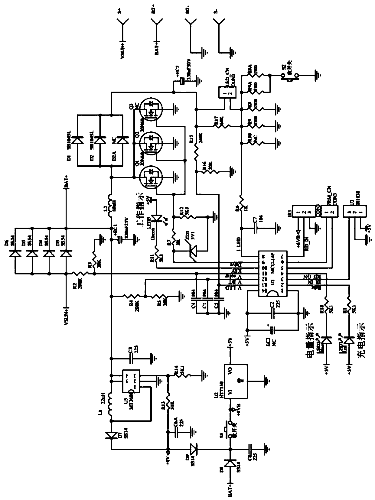
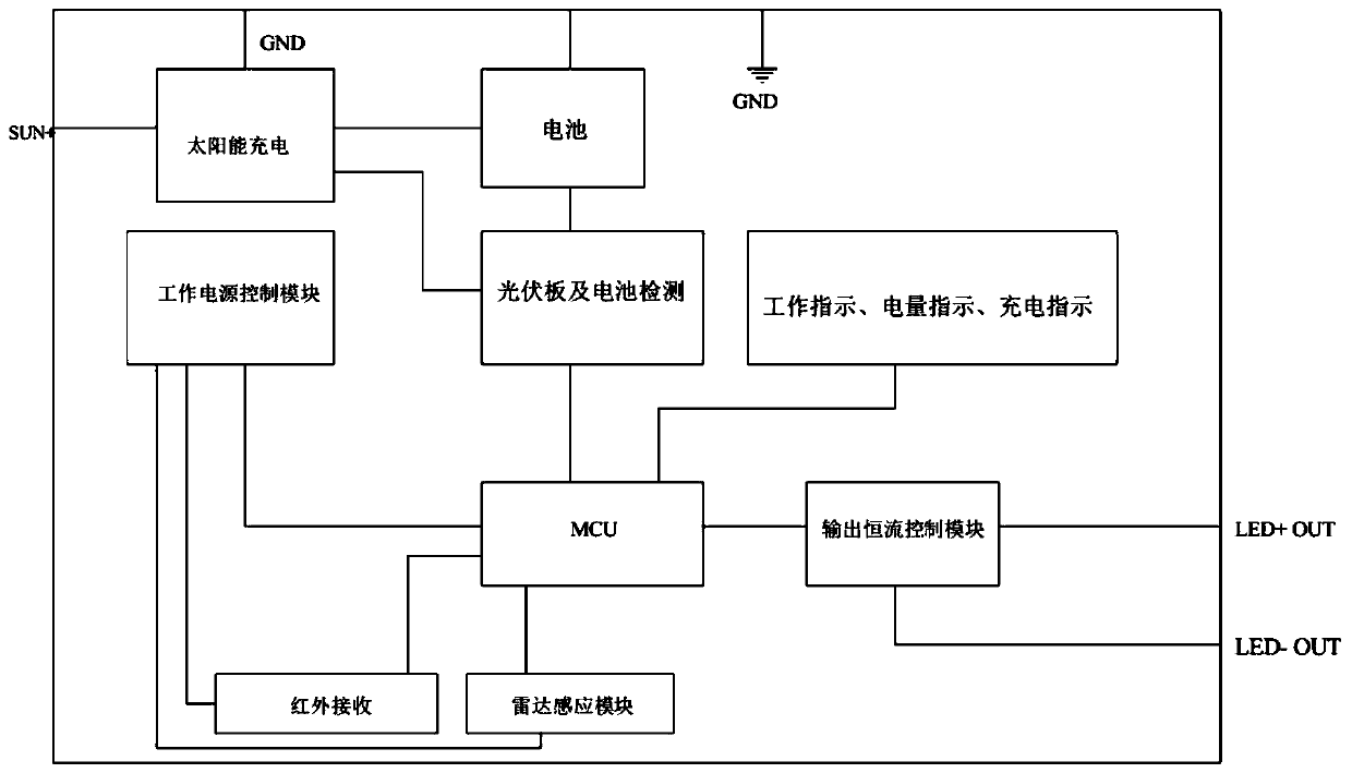
[0025] like figure 1 and figure 2 As shown, the present invention proposes a universal solar control system, including solar charging circuit, battery pack, photovoltaic panel and battery detection circuit, working power control circuit, infrared receiving circuit, radar induction circuit, MCU, output boost constant current control Circuit and indication circuit, solar charging circuit is respectively connected with battery pack, ph...


PUM


Abstract

The invention discloses a universal solar control system, comprising a solar charging circuit, a battery pack, a photovoltaic panel, a battery detecting circuit, a working power supply control circuit, an infrared receiving circuit, a radar sensing circuit, an MCU, an output boosting constant current control circuit, and an indicating circuit, wherein the solar charging circuit is respectively connected with the battery pack, the photovoltaic panel and the battery detecting circuit, the photovoltaic panel and the battery detecting circuit are connected with the MCU, the MCU is respectively connected with the working power supply control circuit, the infrared receiving circuit, the radar sensing circuit, the output boosting constant current control circuit and the indicating circuit, and the output boosting constant current control circuit is connected with an LED load. The system adopts the high-speed MCU, in combination with an auxiliary boosting circuit and the output boosting constant current control circuit, to avoid a flashing light phenomenon generated when the change of a battery voltage needs to be changed in a lamp turning on process by using a simple but quite intelligentprocessing manner in a process of implementing constant current output, and reduces dedicated constant current IC circuits added for input battery boosting or output, thereby greatly reducing the system cost.

Description

technical field [0001] The invention relates to a universal solar control system. Background technique [0002] At present, the lithium battery solar lighting control systems on the market are control systems developed for different battery voltages, and adopt the step-down current limiting method. The resistance current-limiting method supplies power to the load, so that when the battery voltage is fully charged (about 3.4V) and the battery power becomes low (such as 2.8V), the output current also decreases, making the brightness of the lamp very different. [0003] The resistance current-limiting method is adopted because the power consumption of the current-limiting resistor is relatively large, so that the conversion efficiency of input / output is low, and electric energy is wasted. The heat generation of the current limiting resistor is also very large, which increases the cooling cost of the control system and limits the development of high-power output. At present, th...

Claims


Application Information

Patent Timeline
IPC IPC(8): H05B33/08H02J7/35H02J7/00H05B44/00
CPCY02E10/56
Inventor 罗辉荣
Owner 中山市核芯动力电子科技有限公司
Why Eureka
Try Eureka