Ceramic body defect inspecting device and defect inspecting method

一种缺陷检查、陶瓷体的技术,应用在端面的装置领域,能够解决凹凸部分误检测为缺陷、凹凸部分易产生阴影等问题

Active Publication Date: 2019-06-21
NGK INSULATORS LTD
View PDF8 Cites 7 Cited by
  • Summary
  • Abstract
  • Description
  • Claims
  • Application Information

AI Technical Summary

Problems solved by technology

[0009] For example, if oblique light illumination as disclosed in Patent Document 2 is used for defect inspection, there is a problem that although it is known that defective parts such as notches and pits tend to become dark parts (shadows), on the other hand, in normal Concave and convex parts are also prone to shadows, so when detecting defects based on the presence or absence of dark parts, there is a high possibility that normal concave and convex parts will be erroneously detected as defects

Method used


Image

  • Ceramic body defect inspecting device and defect inspecting method
  • Ceramic body defect inspecting device and defect inspecting method
  • Ceramic body defect inspecting device and defect inspecting method

Examples


no. 1 approach >

[0079]

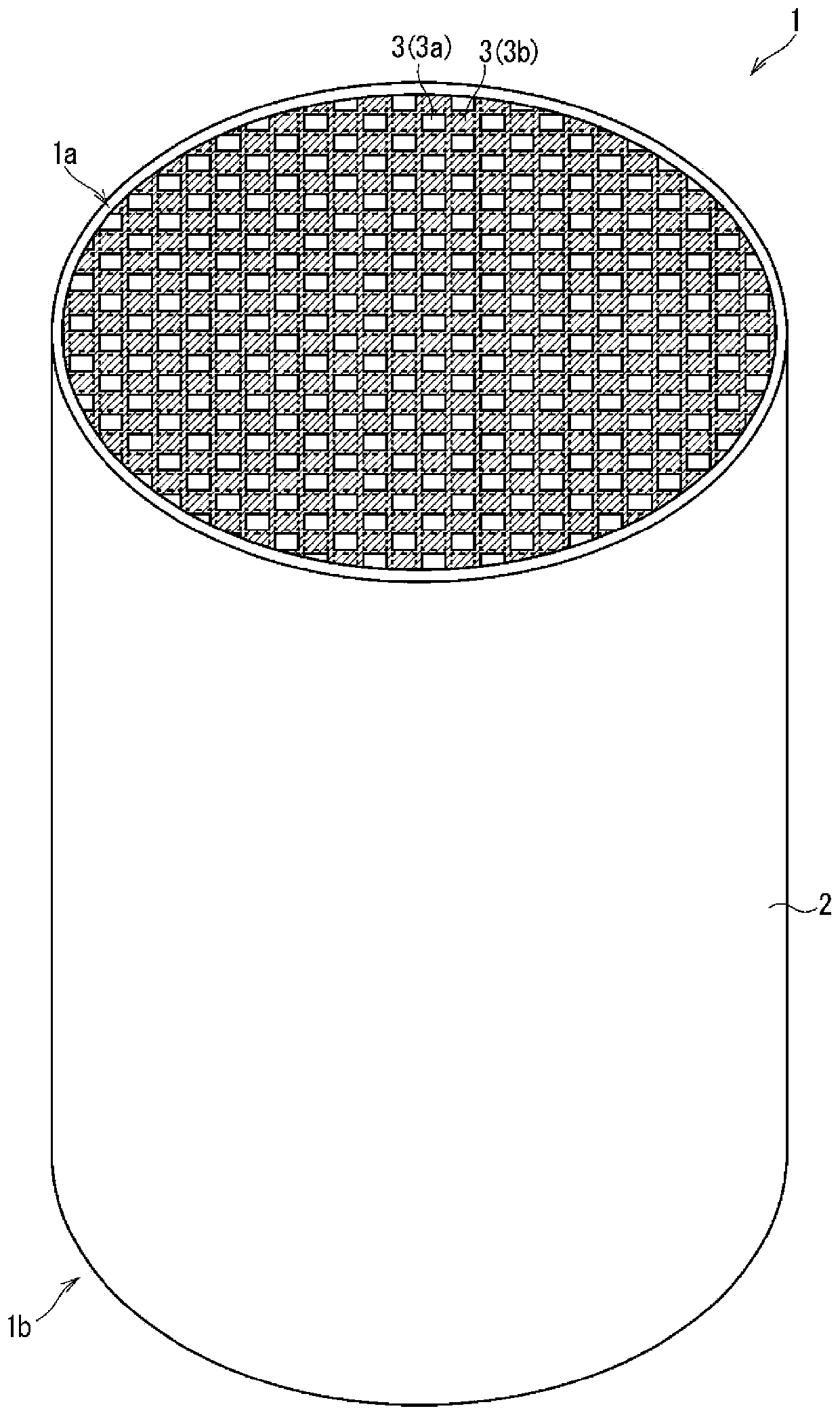
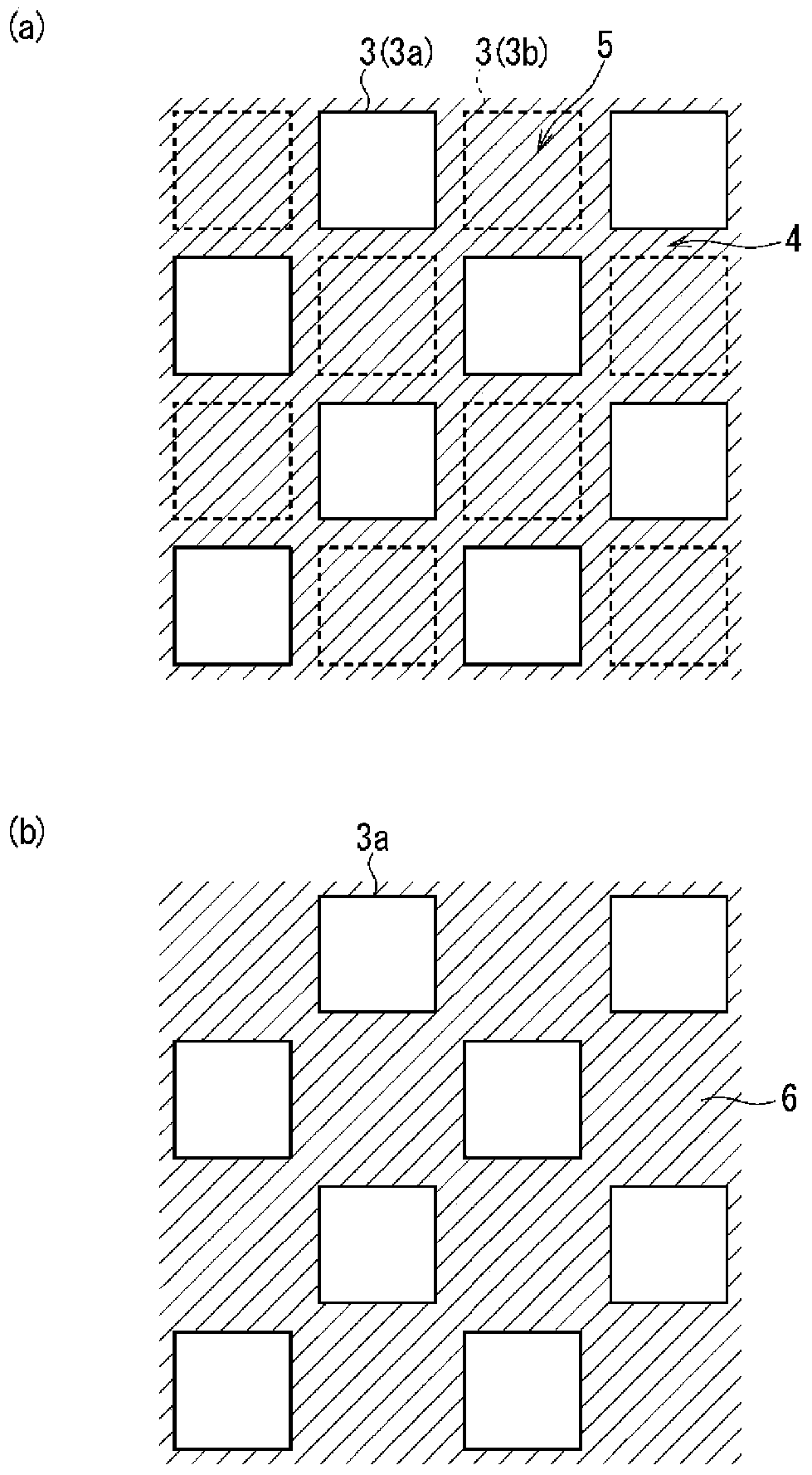
[0080] First, the honeycomb structure whose end surface is the object of defect inspection in this embodiment will be described. figure 1 It is a perspective view of the appearance of the honeycomb structure 1. figure 2 This is a partially enlarged schematic diagram of one end surface 1a of the honeycomb structure 1.

[0081] The honeycomb structure 1 is a cylindrical ceramic structure (ceramic body) having a so-called honeycomb structure inside. The honeycomb structure 1 has a plurality of cells 3 in the shape of a quadrangular prism (square in cross section) in the inside surrounded by an outer wall 2 having a cylindrical shape. Each cell 3 is divided by the partition wall 4 (refer to figure 2 (A)) is divided into sections and is along the direction (axial direction) of the central axis of the honeycomb structure 1. However, the cells 3 may be formed in an oblique prism shape whose longitudinal direction is inclined with respect to the central axis of the honeycomb s...

no. 2 approach >

[0270]

[0271] In the method of defect inspection using the defect inspection apparatus 1000 or 2000 described in the first embodiment, in principle, the size of the honeycomb structure 1 to be inspected is not limited. That is, as long as the imaging execution unit 100 (especially the first lighting unit 120 and the second lighting unit 130) of the defect inspection device 1000 or 2000 is configured to match the size of the honeycomb structure 1, no matter what size the honeycomb structure 1 is , It should be able to perform defect inspection based on the method of the first embodiment. Alternatively, even when the inspection target area is smaller than the size of the end face 1a of the honeycomb structure 1, by repeating the defect inspection multiple times while moving the inspection target area, it is possible to perform the defect inspection of the entire end face 1a.

[0272] In this case, the inspection target area becomes larger. Specifically, as the field of view (imag...


PUM

PropertyMeasurementUnit
lengthaaaaaaaaaa

Abstract

The invention provides a ceramic body defect inspecting device and a defect inspecting method. Around an image capturing unit which captures images of an inspection target region from a normal line direction thereof, a plurality of unit lights, which are at equiangular intervals from one another, and each of which radiates illuminating light obliquely, with the same radiation angle, toward the inspection target region from a different radiation direction, are successively turned on and off. Each time each of the plurality of unit lights is turned on, the image generating unit captures an imageof the inspection target region, thereby generating a plurality of sets of image-capture data. A determination image generating unit generates minimum brightness image data in which the minimum valueof the brightness at the same pixel position from among the plurality of sets of image-capture data is set as a brightness value at said pixel position, and generates determination image data on thebasis of the minimum brightness image data. A defect determining unit determines the presence or absence of a defect on the basis of the determination image data.

Description

Technical field [0001] The present invention relates to a device and method for detecting whether there are defects on the outer surface of a ceramic body, and in particular to a device and method for detecting the end surface of a honeycomb structure. Background technique [0002] As a filter for trapping particulate matter contained in exhaust gas from internal combustion engines, boilers, etc., and a catalyst carrier for exhaust gas purification catalysts, honeycomb structures that are porous bodies (ceramic bodies) made of ceramics are widely used. The honeycomb structure has a plurality of cells divided by partition walls each along the axial direction of the structure in the inside surrounded by the cylindrical outer surface (outer wall). The ceramic honeycomb structure is excellent in heat resistance, thermal shock resistance, and oxidation resistance, and therefore it is widely used in other applications than the above-mentioned applications. [0003] In such a honeycomb s...

Claims


Application Information

Patent Timeline
Patent Type & Authority Applications(China)
IPC IPC(8): G01N21/95F01N3/022F01N11/00
CPCF01N3/022F01N11/00G01N21/95692G01N21/952G01N21/8806G01N21/9515G01N21/95Y02T10/40G06T5/50G06T2207/20221G06T2207/20212G06T7/11G06T7/194G06T7/136G06T7/0002G06T2207/10152G06T7/174
Inventor 小濑木杏菜水谷彰宏寺拝贵史
Owner NGK INSULATORS LTD
Why Eureka
Try Eureka