Optical image stabilization method and system based on line scanning imaging system

An imaging system, line scanning technology, applied in the parts of TV systems, medical science, image communication, etc., can solve problems such as optics and control defects, and achieve the effect of improving spatial accuracy and temporal bandwidth

Pending Publication Date: 2019-06-25
BRIGHTVIEW MEDICAL TECH NANJING CO LTD
View PDF8 Cites 13 Cited by
  • Summary
  • Abstract
  • Description
  • Claims
  • Application Information

AI Technical Summary

Problems solved by technology

[0003] In view of this, the main purpose of the present invention is to provide an optical image stabilization method and system based on a line scan imaging system (LSO), which aims to overcome the inherent optical and control defects of the existing LSO system, and greatly improve its clinical application. Stability, accuracy, imaging efficiency in application

Method used


Image

  • Optical image stabilization method and system based on line scanning imaging system
  • Optical image stabilization method and system based on line scanning imaging system
  • Optical image stabilization method and system based on line scanning imaging system

Examples


Embodiment Construction

[0040] The present invention will be further described in detail below in conjunction with the drawings and embodiments of the present invention.

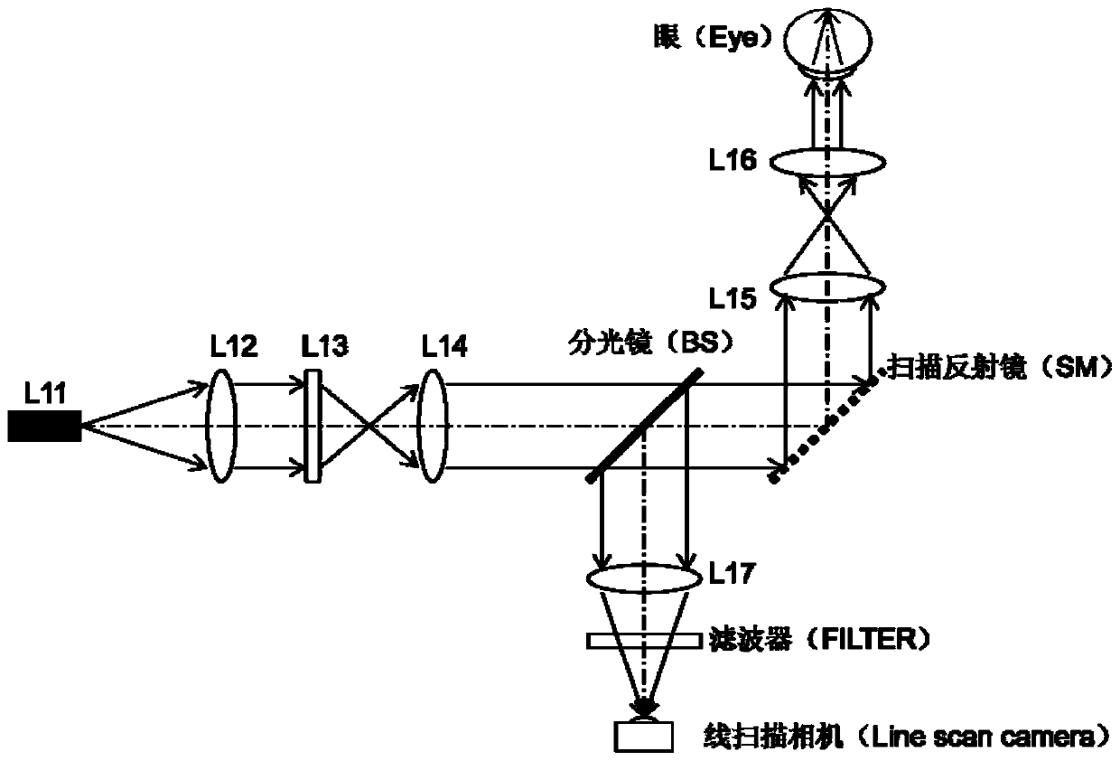
[0041] figure 1 It is a schematic diagram of the optical structure of an existing line scan fundus camera.

[0042] Such as figure 1 As shown, the light emitted from the point light source L11 is collimated by the lens L12, and the surface light source is converted into a line light source through a cylindrical lens (Cylinder Lens) L13, and then continues to be relayed to the collimating lens L14. Here, the installation direction of the cylindrical mirror L13 determines the expansion direction of the line light source in space (see Picture 9 with Picture 10 ), the lens L12, the lens L13, and the lens L14 determine to a certain extent the illumination (expansion) size of the line light source in the fundus. Part of the light emitted by the lens L14 passes through the beam splitter (BS) and reaches the scanning mirror (Steering Mirror o...


PUM


Abstract

The invention discloses an image stabilization method and system based on a line scanning imaging system. The system comprises a main line scanning imaging system (LSO) with internal optical closed loop tracking and an integrated LSO controlled auxiliary imaging system. The main LSO imaging system is used for self imaging, providing fundus positioning and navigation for the auxiliary imaging system, obtaining fundus or eye movement information from an LSO image and performing closed-loop optical tracking. The auxiliary imaging system makes light from a point source reach an orthogonal scanningmirror through a collimation system and focus on a dichroic mirror (DM). The corresponding spatial position of the orthogonal scanning mirror is adjusted in real time by applying the fundus or eyeball motion information to the orthogonal scanning mirror to obtain a tomographic image of the desired fundus position or achieve point and array target hitting of the fundus. By means of the method, a closed-loop fundus optical tracking system can be established in the LSO, and the closed-loop tracking system is utilized to control the line scanning imaging system to achieve the aim of high speed, stability and accurate control.

Description

Technical field [0001] The invention relates to laser fundus target tracking and imaging technology, in particular to an optical image stabilization method and system based on a line scan imaging system. Background technique [0002] The existing target tracking technology based on the Line Scan Ophthalmoscope (LSO) imaging system, such as the imaging system of Carl Zeiss, uses one frame of image as a unit to calculate the amount of movement of the fundus target. However, there is a defect that the control system has a time delay of at least one frame, which leads to a decrease in tracking accuracy. Moreover, the existing LSO target tracking signal method is completely digital. When extracting the signal from the image, due to the lack of optical closed-loop control measures inside the LSO, the calculation of the fundus motion signal is not very reliable. Summary of the invention [0003] In view of this, the main purpose of the present invention is to provide an optical image st...

Claims


Application Information

Patent Timeline
Patent Type & Authority Applications(China)
IPC IPC(8): A61B3/12A61B3/14
CPCA61B3/12A61B3/14A61B3/1025A61B3/113A61B3/102H04N23/6812
Inventor 张杰张金莲
Owner BRIGHTVIEW MEDICAL TECH NANJING CO LTD
Why Eureka
Try Eureka