A pressure relief joint and a liquid cooling assembly using the pressure relief joint

A component and liquid cooling technology, which is applied in the direction of engine components, cooling/ventilation/heating modification, valve device, etc., can solve problems such as the inability to guarantee the sealing of liquid cooling components in the box, and the decrease of spring elasticity

Active Publication Date: 2021-03-23
CHINA AVIATION OPTICAL-ELECTRICAL TECH CO LTD
View PDF4 Cites 0 Cited by
  • Summary
  • Abstract
  • Description
  • Claims
  • Application Information

AI Technical Summary

Problems solved by technology

However, in the prior art, after working for a long time, the elastic force of the spring decreases. If there is a small pressure fluctuation in the box during normal use, it may cause the opening of the pressure relief valve, causing the cooling liquid to flow out, and it is impossible to guarantee the normal operation of the box. body or other liquid-cooled components

Method used


Image

  • A pressure relief joint and a liquid cooling assembly using the pressure relief joint
  • A pressure relief joint and a liquid cooling assembly using the pressure relief joint
  • A pressure relief joint and a liquid cooling assembly using the pressure relief joint

Examples


specific Embodiment 1

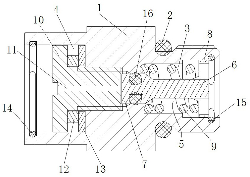
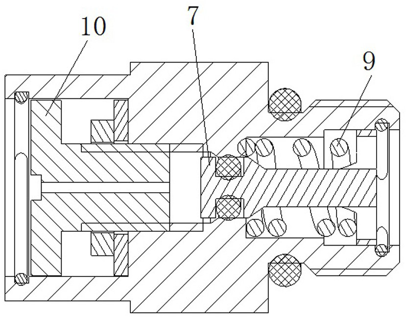
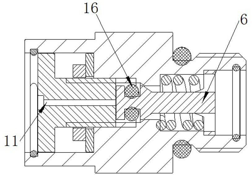
[0027] Such as Figure 1 to Figure 3 As shown, the pressure relief joint includes a joint seat 1, and the outside of the right end of the joint seat 1 along the axial direction is provided with threads for assembling on the coolant cavity, and a housing sealing ring 2 is installed on the joint seat 1 to prevent the coolant from The coolant in the cavity flows out through the pressure relief joint to ensure the airtightness of the coolant cavity.

[0028] The joint seat 1 has an axial through hole for communicating with the coolant cavity, and the axial through hole includes a valve core installation section 3 for installing a valve core and a screw installation section 4 for installing a locking screw. The spool installation section 3 includes a spring installation section with a larger aperture and a spool sealing section with a smaller aperture. A pressure relief spool 5 is installed along the axial movement guide in the spool installation section 3. The pressure relief spoo...

specific Embodiment 2

[0036] Such as Figure 4 As shown, the difference from Embodiment 1 is that in this embodiment, a blocking rod 17 is installed radially on the joint seat 1, and the way that the blocking rod 17 is assembled on the joint seat 1 can be threaded installation or other activities. way of installation. Figure 4 In the process, the blocking rod 17 and the pressure relief valve core 5 stop and cooperate to prevent the pressure relief valve core 5 from continuing to move to the left for pressure relief. When debugging or transporting the liquid-cooled component, or when the liquid-cooled component is in a high-temperature working environment, in order to prevent the pressure of the coolant inside the liquid-cooled component from increasing sharply and not being released. The retaining rod 17 is removed from the left end of the pressure relief spool 5, and the pressure relief spool 5 can perform normal pressure relief and blocking.

[0037] In this embodiment, the blocking rod 17 con...


PUM


Abstract

The invention relates to a pressure relief joint and a liquid cooling component using the same in order to guarantee the leakproofness of the liquid cooling component in normal work. The pressure relief joint comprises a joint seat which is hermetically installed on a cooling liquid chamber body; the joint seat is provided with a pressure relief passage which communicates with the inside of the cooling liquid chamber body; the pressure relief joint further comprises a pressure relief valve core which is movably installed inside the joint seat in a guiding manner; the pressure relief valve corecomprises a sealing position and a pressure relief position, wherein the sealing position is positioned in a movement stroke and is used for sealing the pressure relief passage; the pressure relief position is used for opening the pressure relief passage; the pressure relief joint further comprises a locking part which is used for matched with the pressure relief valve core in a stop manner in order to keep the pressure relief valve core at the sealing position; the locking part is detachably installed or movably installed on the joint seat; and the locking part which is movably installed onthe joint seat comprises an avoiding position which is separated from the pressure relief valve core in a stop manner. By additionally arranging the locking part, the pressure relief joint has the pressure relief function without affecting the normal use of the liquid cooling component, and does not cause leakage of cooling liquid.

Description

technical field [0001] The invention relates to a pressure relief joint and a liquid cooling assembly using the pressure relief joint. Background technique [0002] For electronic equipment using liquid cooling, when it is necessary to debug or transport the liquid cooling components, the liquid cooling components are usually disassembled from the equipment. After disassembly, the inside of the liquid cooling components is a closed space filled with liquid . When the temperature of the external environment rises, the liquid pressure inside the liquid-cooled component will increase sharply. In extreme cases, the flow channel in the liquid-cooled cold plate will bulge, the seal will fail, and leakage will occur. In order to prevent this problem from happening, the operator needs to drain the disassembled liquid cooling components one by one, so as to avoid the pressure increase of the liquid inside the liquid cooling component as the temperature increases, but this operation ...

Claims


Application Information

Patent Timeline
Patent Type & Authority Patents(China)
IPC IPC(8): F16K17/04H05K7/20
Inventor 赵颍杰杨安礼
Owner CHINA AVIATION OPTICAL-ELECTRICAL TECH CO LTD
Why Eureka
Try Eureka