
Vertical screening-net-free discharging medium stirring mill

A screenless, stirring mill technology, applied in grain processing and other directions, can solve the problems of separation device failure, reduced grinding efficiency, low discharge efficiency, etc., and achieve the effects of uniform particle grinding, high production efficiency, and large discharge flow.

Inactive Publication Date: 2019-06-28
深圳市微纳达智能设备有限公司
View PDF4 Cites 0 Cited by
  • Summary
  • Abstract
  • Description
  • Claims
  • Application Information

AI Technical Summary

Problems solved by technology

The dynamic and static ring separation method only forms an annular discharge gap between the dynamic ring and the static ring. Due to the limited discharge space, under the action of the feed pump, a lot of slurry accumulates around the separator and rubs against each other to generate a lot of heat. The temperature of the slurry rises and at the same time blocks each other, resulting in a decrease in grinding efficiency
Although the pipe network static separation method can increase the discharge space according to the increase of the diameter of the pipe network or the length of the pipe network, due to the static discharge method, when encountering a slurry with high viscosity or high consistency, the viscous The material will block the mesh due to adhesion, making the separation device ineffective
Due to the low discharge efficiency of the original two separation methods and the repeated grinding of the materials retained in the grinding chamber, the temperature of the slurry in the grinding chamber is too high, which limits the grinding of some heat-sensitive materials.

Method used


Image

  • Vertical screening-net-free discharging medium stirring mill
  • Vertical screening-net-free discharging medium stirring mill
  • Vertical screening-net-free discharging medium stirring mill

Examples


Embodiment Construction

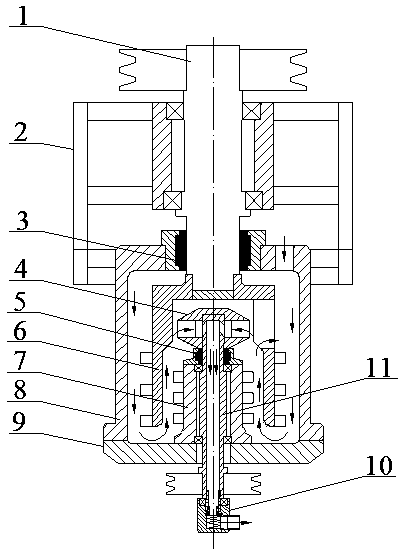
[0017] In order to better understand the present invention, the present invention will be further described below in conjunction with the accompanying drawings. Such as figure 1 As shown, in the vertical non-screen discharge medium stirring mill of the present invention, the transmission shaft (1) is vertically fixed on the transmission seat (2), and the upper mechanical seal (3) and the stirring rotor ( 6). The cylindrical grinding chamber (8) is fixed on the transmission seat (2), and forms a closed grinding space with the cylinder head (9).

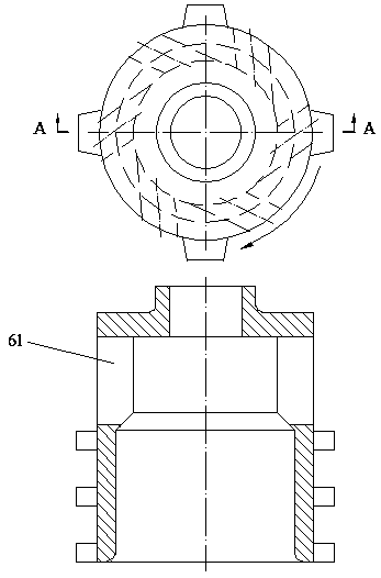
[0018] The upper part of the stirring rotor (6) has several grinding vortex grooves (61) to form a turbine structure, and the lower part is a rotor with several pins evenly distributed. When the main shaft rotates, the grinding vortex grooves (61) on the stirring rotor (6) ) produces a strong centrifugal force to drive the slurry and grinding media to move radially and circularly and drive them to flow down the cylinder wall. Due to ...


PUM


Abstract

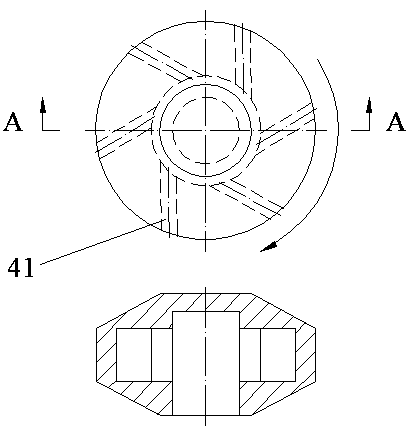
A vertical screening-net-free discharging medium stirring mill comprises a transmission shaft, a transmission seat, an upper mechanical seal, a separating turbine, a lower mechanical seal, a stirringrotor, an inner stator, a cylindrical milling chamber, a cylinder cover, a discharging rotating head and a discharging spindle, wherein the stirring rotor and the cylindrical milling chamber for man outer circulating milling area, and the inner wall of the stirring rotor and the inner stator form an inner circulating milling area; the inner circulating milling area and the outer circulating milling area are combined, so that the milling effect is improved, and the structure is compact; a plurality of separating vortex grooves are formed in the separating turbine and are capable of generating high centrifugal force during rotating, so that a milling medium and slurry can be effectively separated, and materials can be discharged without a screening net.

Description

technical field [0001] The invention belongs to the field of media agitation and grinding equipment, and in particular relates to a vertical media agitation mill without screen mesh discharge. Background technique [0002] At present, the conventional horizontal medium stirring mill discharge methods mainly include dynamic and static ring dynamic separation methods and pipe network static separation methods, which are widely used in coatings, inks, dyes, mining, biology, medicine, and electronic materials. in the grinding field. The dynamic and static ring separation method only forms an annular discharge gap between the dynamic ring and the static ring. Due to the limited discharge space, under the action of the feed pump, a lot of slurry accumulates around the separator and rubs against each other to generate a lot of heat. The temperature of the slurry increases and at the same time blocks each other, resulting in a decrease in grinding efficiency. Although the pipe net...

Claims


Application Information

Patent Timeline
Patent Type & Authority Applications(China)
IPC IPC(8): B02C17/16
Inventor 李茜
Owner 深圳市微纳达智能设备有限公司
Learn More