
Liquid crystal display panel line laser cutting machine

A liquid crystal panel and cutting machine technology, applied in welding equipment, laser welding equipment, metal processing equipment, etc., can solve the problems of high equipment cost, fragile products, high raw material cost, etc., and achieve low equipment investment cost, intelligent and simple operation, The effect of low raw material cost

Pending Publication Date: 2019-06-28
柯尔微电子装备(厦门)有限公司
View PDF0 Cites 3 Cited by
  • Summary
  • Abstract
  • Description
  • Claims
  • Application Information

AI Technical Summary

Problems solved by technology

[0004] In order to solve the above problems, the existing technology can only cut with a single wavelength, is inconvenient to use, has poor versatility, high equipment cost, low equipment utilization rate, only front cutting with large metal residue and easily damaged products, low yield rate, large waste of raw materials, high raw material cost, etc. Problem, the present invention adopts following technical scheme:

Method used

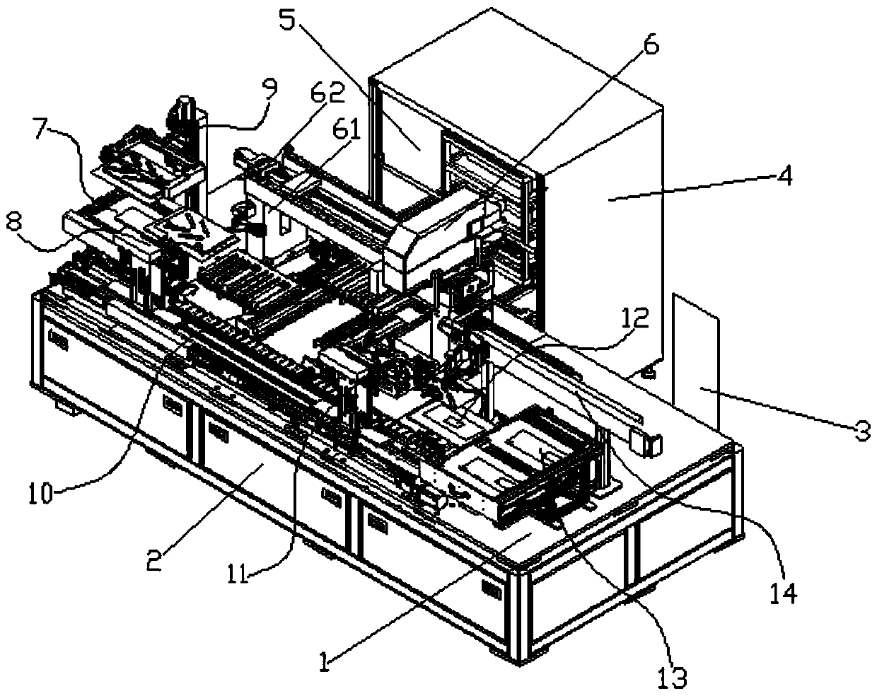

Image

  • Liquid crystal display panel line laser cutting machine
  • Liquid crystal display panel line laser cutting machine
  • Liquid crystal display panel line laser cutting machine

Examples


Embodiment Construction

[0025] Preferred embodiments of the present invention will be described in detail below in conjunction with the accompanying drawings.

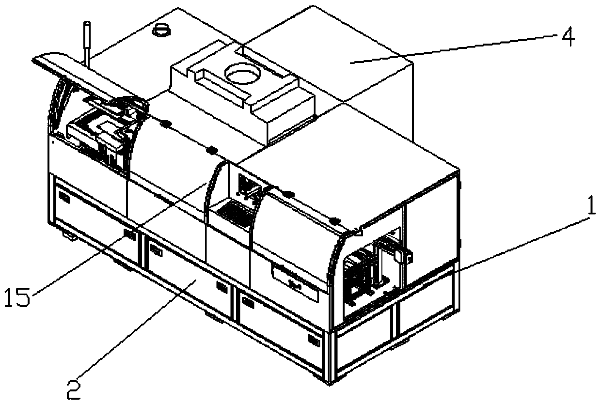
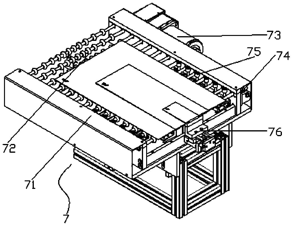
[0026] see figure 1 , a liquid crystal panel line laser cutting machine, including a frame 1, an electric control box 2, a man-machine interface 3, a laser generator box 4, an industrial computer 5, a laser head 6, a material receiving mechanism 7, a material feeding mechanism 8, Flipping mechanism 9, laser stage mechanism 10, unloading mechanism 11, transfer platform 12, NG slice module 13 and discharging mechanism 14, described electric control box 2 is arranged at the bottom of frame 1, and electric control box is used for all The electric equipment performs circuit control, the man-machine interface 3 is set on the side of the frame 1, the man-machine interface sets and adjusts the parameters of the servo motor and the cylinder, and the laser generator box 4 is equipped with a red laser generator. laser generator and a green laser genera...


PUM


Abstract

The invention discloses a liquid crystal display panel line laser cutting machine. The machine comprises a machine frame, an electric cabinet, a human-computer interface, a laser generator box body, an industrial computer, a laser head, a material receiving mechanism, a feeding mechanism, a turnover mechanism, a laser carrying table mechanism, an unloading mechanism, a transferring platform, an NGpiece arranging module, and a discharging mechanism, wherein the material receiving mechanism, the laser carrying table mechanism, the transferring platform and the NG piece arranging module are sequentially arranged on the machine frame, the feeding mechanism and the unloading mechanism are correspondingly located on the left side and the right side of the laser carrying table mechanism, the turnover mechanism is arranged close to the material receiving mechanism, and the discharging mechanism is arranged close to the transferring platform. The machine has the characteristics that the red light and green light can be freely switched and used, the requirements of different products can be met and the use is convenient, the use is not limited and the universality is high, the equipment investment cost is low and the utilization rate is high, front side cutting and reverse side cutting are available, no metal residue is generated and the product is not damaged, the yield is high, the raw material waste is little and the raw material cost is low, the material receiving, feeding, overturning, unloading, discharging and the like are assembled together and are automatically completed, manual operation intervention is not needed, and the operation is intelligent and simple.

Description

technical field [0001] The invention belongs to the field of mechanical equipment, in particular to a laser cutting machine for liquid crystal panel circuits. Background technique [0002] Laser and laser are the same thing. Laser is the name of the mainland, and laser is the transliteration of English laser. The laser cutting currently used is still unable to solve the metal residue. At the same time, there are major defects in the use. Specifically, there are two The reason is that the laser cutting currently used is either red light or green light, and can only cut with a single wavelength, and red light and green light have different characteristics for different metals, so the equipment is very limited when cutting specific products , inconvenient to use and poor versatility, it is necessary to purchase two devices at the same time, the cost of the equipment is high, and the utilization rate of the equipment is low. Completely, it is adsorbed to the surface of the prod...

Claims


Application Information

Patent Timeline
Patent Type & Authority Applications(China)
IPC IPC(8): B23K26/38B23K26/70
Inventor 郑隆结
Owner 柯尔微电子装备(厦门)有限公司
Learn More