Heat pump drying system and control method

A heat pump drying and control method technology, applied in the direction of drying gas arrangement, drying, drying machine, etc., can solve the problems of unable to ensure indoor moisture at the same time, latent heat recovery and drying material heating requirements, etc., to avoid heat waste, avoid Uneven oil return, the effect of improving the energy efficiency of the system

Inactive Publication Date: 2019-06-28
GREE ELECTRIC APPLIANCES INC
View PDF6 Cites 10 Cited by
  • Summary
  • Abstract
  • Description
  • Claims
  • Application Information

AI Technical Summary

Problems solved by technology

[0005] Therefore, the technical problem to be solved by the present invention is to overcome the defects that the heat pump drying system in the prior art cannot simultaneously guarantee the latent heat recovery of indoor moisture and meet the requirements of drying materials to heat up, so as to provide a heat pump drying system and control method

Method used


Image

  • Heat pump drying system and control method
  • Heat pump drying system and control method
  • Heat pump drying system and control method

Examples


Embodiment 1

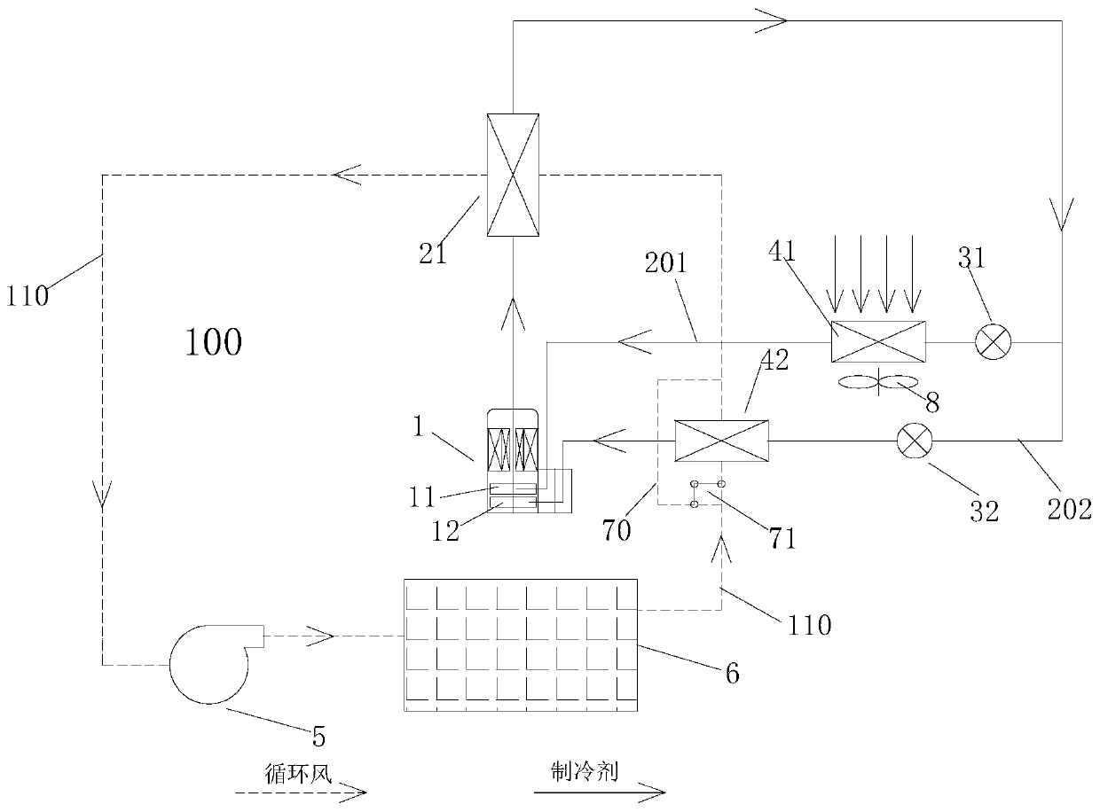
[0074] like figure 1 As shown, the present invention provides a heat pump drying system, which includes:

[0075] Compressor 1, drying device 100, drying condenser 21, outdoor evaporator 41 and indoor evaporator 42, the drying condenser 21 is connected with the exhaust end of the compressor 1, and can control the drying device 100 The outdoor evaporator 41 can be connected to the suction end of the compressor 1 to evaporate and absorb heat from the outside of the drying device 100, and the indoor evaporator 42 can also be connected to the The suction end of the compressor 1 is used to evaporate, absorb heat and dehumidify the air in the drying device 100 .

[0076] In the present invention, the evaporator is divided into an indoor evaporator and an outdoor evaporator, the indoor evaporator is arranged inside the air duct, and the outdoor evaporator is arranged in the environment outside the drying room, that is, one evaporator is respectively arranged inside and outside the d...

Embodiment 2

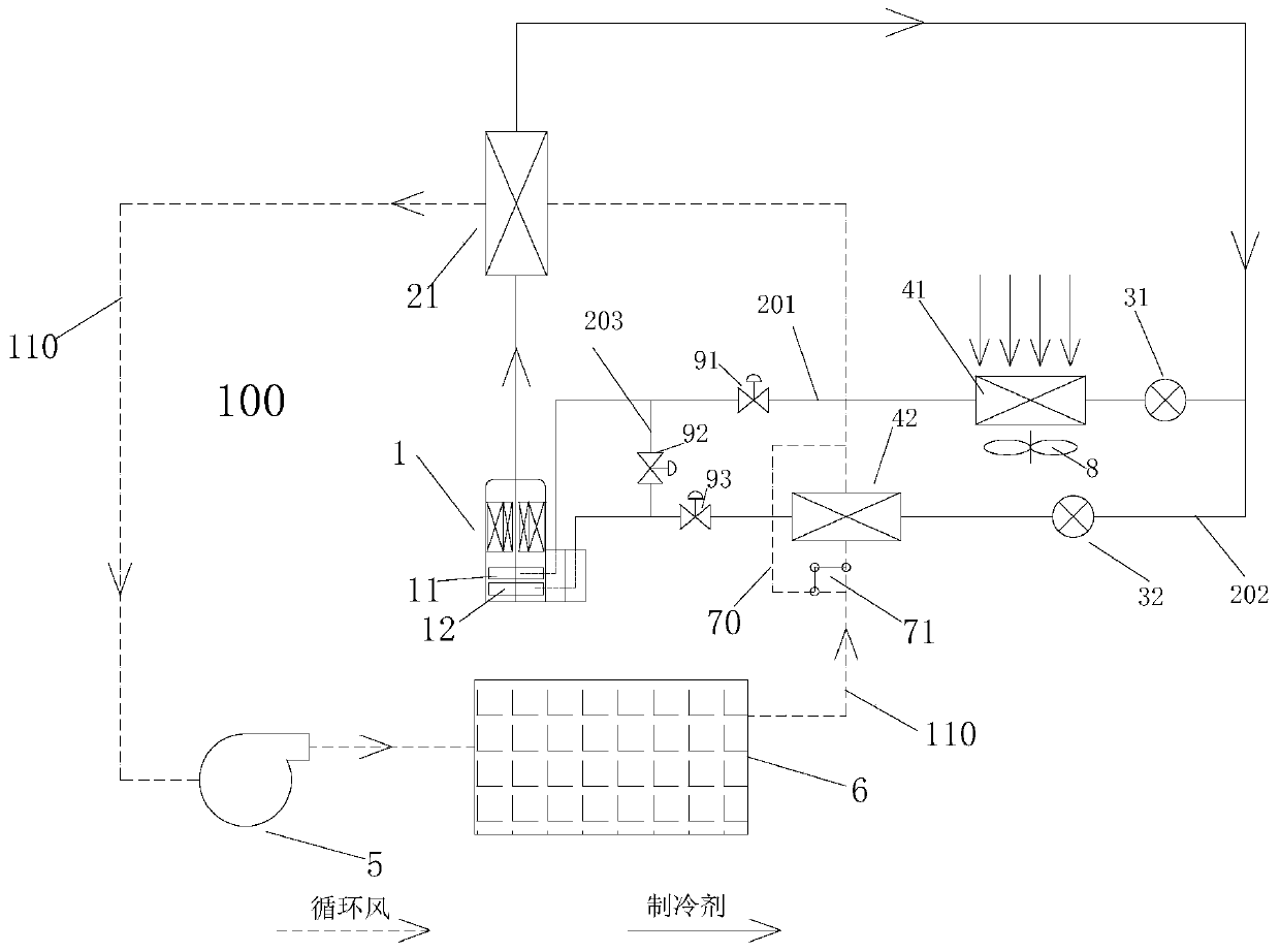
[0092] like figure 2 As shown, this embodiment is a further improvement made on the basis of Embodiment 1, and all the contents of Embodiment 1 are included in this embodiment, preferably,

[0093] A first two-way valve 91 is also provided on the first branch 201 and between the outdoor evaporator 41 and the suction end of the first compression cylinder 11 ;

[0094] A third two-way valve 93 is also provided on the second branch 202 and between the indoor evaporator 42 and the suction end of the second compression cylinder 12 ;

[0095] And the position between the first two-way valve 91 and the suction end of the first compression cylinder 11 and the position between the third two-way valve 93 and the suction end of the second compression cylinder 12 A third branch 203 is connected to the position, and a second two-way valve 92 is also arranged on the third branch 203 .

[0096] The two branches can be controlled separately through the first two-way valve set on the first ...

Embodiment 3

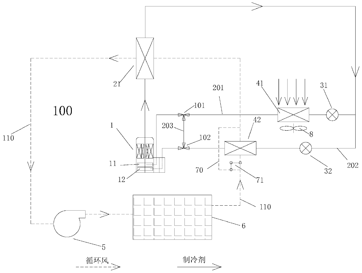
[0104] like Figure 4 As shown, this embodiment is a further improvement made on the basis of Embodiment 1, and all the contents of Embodiment 1 are included in this embodiment, preferably,

[0105] The heat pump drying system also includes an outdoor condenser 22, one end of the outdoor condenser 22 can communicate with the indoor evaporator 42, and the other end can communicate with the second compression cylinder 12; at this time, the drying condenser One end of 21 communicates with the outdoor evaporator 41 , and the other end communicates with the first compression cylinder 11 . By setting an outdoor condenser, part of the high-pressure and high-temperature refrigerant compressed by the compressor can flow through the outdoor condenser to release heat, so that part of the refrigerant flows through the drying condenser to heat the drying device or there is no refrigerant Enter the drying condenser to heat the drying device, so that the effect of constant temperature dehum...


PUM


Abstract

The invention provides a heat pump drying system and a control method. The heat pump drying system comprises a compressor (1), a drying device (100), a drying condenser (21), an outdoor evaporator (41) and an indoor evaporator (42). The drying condenser (21) is connected with the exhaust end of the compressor (1) and can heat air in the drying device (100). The outdoor evaporator (41) can be connected to the air suction end of the compressor (1) so that evaporation heat absorbing can be conducted on the outer portion of the drying device (100). The indoor evaporator (42) can also be connectedto the air suction end of the compressor (1) so that evaporation heat absorbing and dehumidification can be conducted on air in the drying device (100). Through the heat pump drying system and the control method, it can be guaranteed that the system can recycle indoor moisture exhausting latent heat, the material drying temperature rise process requirement can be met as well, and the drying temperature can be controlled while heat waste and surrounding environment pollution are effectively avoided.

Description

technical field [0001] The invention belongs to the technical field of heat pumps, and in particular relates to a heat pump drying system and a control method. Background technique [0002] The existing heat pump drying devices mainly include open system and closed system. The open system is that the outdoor evaporator absorbs heat and transfers the heat to the drying room through the indoor condenser. It is suitable for drying materials with high drying temperature requirements. The disadvantages are It is necessary to discharge high-temperature humid air to the outside to dehumidify, resulting in waste of heat and pollution of the surrounding environment; in a closed system, the humid air passes through the evaporator, then cools down and dehumidifies, and then heats up through the condenser, which can recover the latent heat load of the humid air. The disadvantage is The drying temperature of this system is not controlled, and auxiliary electric heating is needed to meet ...

Claims


Application Information

Patent Timeline
Patent Type & Authority Applications(China)
IPC IPC(8): F26B21/00F26B21/08F26B21/12F25B5/02F25B31/00F25B41/04F25B41/06F25B49/02F25B41/20F25B41/30
CPCF26B21/00F25B49/02F26B21/12F25B5/02F26B21/08F25B31/00F25B41/20F25B41/24
Inventor 吕如兵郑波梁祥飞汤康
Owner GREE ELECTRIC APPLIANCES INC
Why Eureka
Try Eureka