Eelectronic equipment with a line detection function

A technology of electronic equipment and texture, applied in the direction of light guide of lighting system, acquisition/organization of fingerprints/palmprints, instruments, etc., can solve the problems of insufficient fingerprint recognition accuracy, insufficient collection, recognition errors, etc., and achieve sufficient detection light intensity. , the effect of high signal-to-noise ratio and high utilization of light energy

Active Publication Date: 2019-06-28
HUAWEI TECH CO LTD
View PDF5 Cites 12 Cited by
  • Summary
  • Abstract
  • Description
  • Claims
  • Application Information

AI Technical Summary

Problems solved by technology

The setting of the imaging optical path makes the light that finally enters the image sensor only account for a very small part of the emitted light. Therefore, the smart phone is prone to lack of fingerprint recognition accuracy due to insufficient light collected by the image sensor, and recognition errors or unrecognizable phenomena occur.

Method used


Image

  • Eelectronic equipment with a line detection function
  • Eelectronic equipment with a line detection function
  • Eelectronic equipment with a line detection function

Examples


Embodiment approach

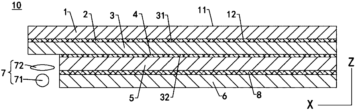
[0136]In one implementation manner, grating grooves of a plurality of first gratings 331 are processed on the base of the light guide plate 3 to form grating teeth of a plurality of first gratings 331 . The grating teeth and the grating grooves of the first grating 331 are arranged alternately in the same layer. The first base 334 is the base of part of the light guide plate 3 laminated with the first grating 331 . Wherein, the grating grooves of the first grating 331 are filled with air. When the top surface 31 of the light guide plate 3 is connected to the cover plate 1 through the first adhesive layer 2 , part of the first adhesive layer 2 is filled in the grating grooves of the plurality of first gratings 331 . At this time, the processing method of the first grating 331 is relatively simple, which is also beneficial to reduce the processing cost of the light guide plate 3 .

[0137] In another embodiment, multiple grating grooves of the first grating 331 are processed o...

other Embodiment approach

[0185] In other embodiments, the first grating part 33 can also be placed corresponding to the lower left corner of the cover plate 1, the second grating part 34 can be placed corresponding to the left edge of the cover plate 1, and the third grating part 35 is located at the second grating part 34 or the first grating part 33 can also be placed corresponding to the upper right corner or lower right corner of the cover plate 1, the second grating part 34 can be placed corresponding to the right edge of the cover plate 1, and the third grating part 35 is located on the second The left side of the grating part 34 .

[0186] Optionally, in a direction parallel to the light-emitting surface 346 of the second grating portion 34 and away from the light-incident surface 345 of the second grating portion 34 (such as Figure 12 As indicated by the straight line with an arrow in the middle), the diffraction efficiency of the second grating portion 34 increases gradually. For example, t...

other Embodiment approach

[0212] In other embodiments, among the two groups of axisymmetric grating groups 30 , the first grating part 33 of one group of grating groups 30 is placed corresponding to the right edge (or left edge) of the middle part of the cover plate 1 . The second grating portion 34 is placed corresponding to the middle of the cover plate 1 . The first grating portion 33 is located between the second grating portion 34 and the first long side 122 (or the second long side 124 ). The third grating portion 35 is located on the top side of the second grating portion 34 . The third grating portion 35 is located between the second grating portion 34 and the first short side 121 .

[0213] The first grating part 33 of the other grating group 30 is placed corresponding to the right edge (or left edge) of the middle part of the cover plate 1 . The second grating portion 34 is placed corresponding to the middle of the cover plate 1 . The first grating portion 33 is located between the second ...


PUM


Abstract

The embodiment of the invention discloses electronic equipment with a line detection function. The electronic equipment comprises a cover plate, a first bonding layer, a light guide plate, a second bonding layer and a display panel which are sequentially stacked. The refractive index of the first bonding layer and the refractive index of the second bonding layer are both smaller than the refractive index of the light guide plate. The electronic equipment also includes an image sensor and a light source. Each grating group of the light guide plate comprises a first grating part, a second grating part and a third grating part, and the area of the emergent surface of the third grating part is larger than that of the incident surface of the first grating part. The emitted light of the light source can enter the first grating part through the light incident surface of the first grating part, passes through the second grating part and the third grating part and then is emitted out through the light emergent surface of the third grating part, and the emitted light enters the cover plate and is totally reflected by the top surface of the cover plate or reflected by lines to be measured toform reflected light. The image sensor is used for receiving the reflected light to form image data of the to-be-detected lines. The electronic equipment is relatively high in identification precision.

Description

technical field [0001] The present application relates to the technical field of electronic products, in particular to an electronic device with a texture detection function. Background technique [0002] As a means of identification, fingerprint recognition technology is widely used in various fields due to its convenience and uniqueness, and has gradually become the basic configuration of electronic devices such as smart phones. [0003] At present, the full screen design is the development trend of smart phones. In order to realize a full screen, some manufacturers set up an image sensor under the screen. When the emitted light of the screen is reflected by the user's finger, the image sensor collects the reflected light passing through the screen to form a fingerprint image to complete the identification. However, since the emitted light of the screen has the characteristics of a Lambert light source, an imaging optical path needs to be added between the image sensor an...

Claims


Application Information

Patent Timeline
Patent Type & Authority Applications(China)
IPC IPC(8): G06K9/00
CPCG06V40/1318G06V10/17G02F1/133624G02B6/0038G02B6/005G02F1/133615G02F1/13362
Inventor 魏文雄王帆沈奥张宏海
Owner HUAWEI TECH CO LTD
Why Eureka
Try Eureka