Plastic garbage crushing device

A technology of plastic waste and crushing device, applied in the direction of magnetic separation, solid separation, press, etc., can solve the problems of insufficient crushing degree, separation, large size of fragments and so on

Active Publication Date: 2019-07-02
江苏伟曜塑胶科技有限公司
View PDF4 Cites 2 Cited by
  • Summary
  • Abstract
  • Description
  • Claims
  • Application Information

AI Technical Summary

Problems solved by technology

Although the above disposal methods will inevitably have an impact on the environment, landfill and incineration will still be the most important disposal methods until a more reasonable and large-scale disposal method is found.
[0003] At present, when plastic waste is landfilled in China, it is usually directly landfilled, and crushing devices are rarely used to crush plastic waste before landfilling.
Moreover, although some plastic waste crushing devices have also appeared on the market at present, these crushing devices generally have the following disadvantages: (1) plastic waste is usually mixed with a large amount of liquid, and the existing crushing devices cannot effectively crush the plastic waste during the crushing process. Separate these liquids from the garbage, and then treat them separately; (2) The degree of fragmentation is not enough, and the size of the fragments is large, resulting in a large gap between the fragments during landfill, which will increase the landfill required.

Method used


Image

  • Plastic garbage crushing device
  • Plastic garbage crushing device
  • Plastic garbage crushing device

Examples


Embodiment 1

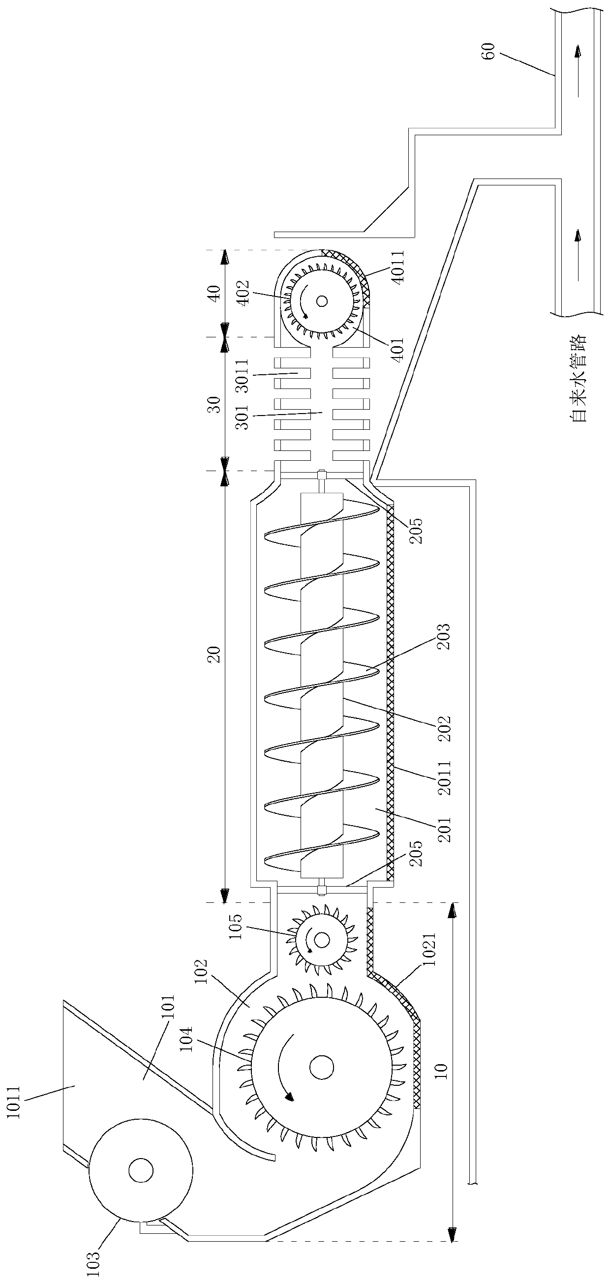
[0043] Such as Figure 1-Figure 7 As shown, the present embodiment provides a plastic waste crushing device, which includes a first segment 10 , a second segment 20 , a third segment 30 and a fourth segment 40 in which the shells are sequentially connected.

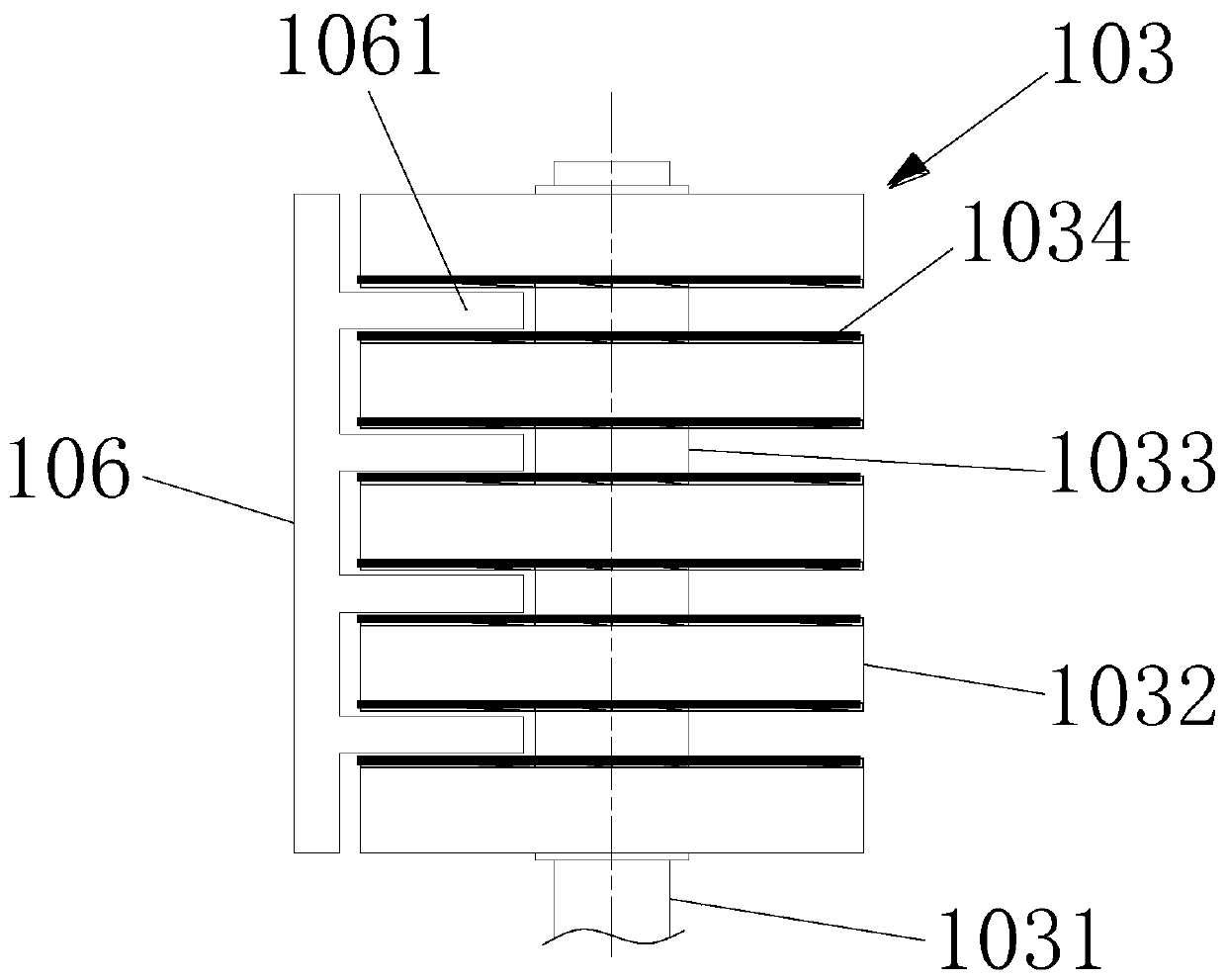
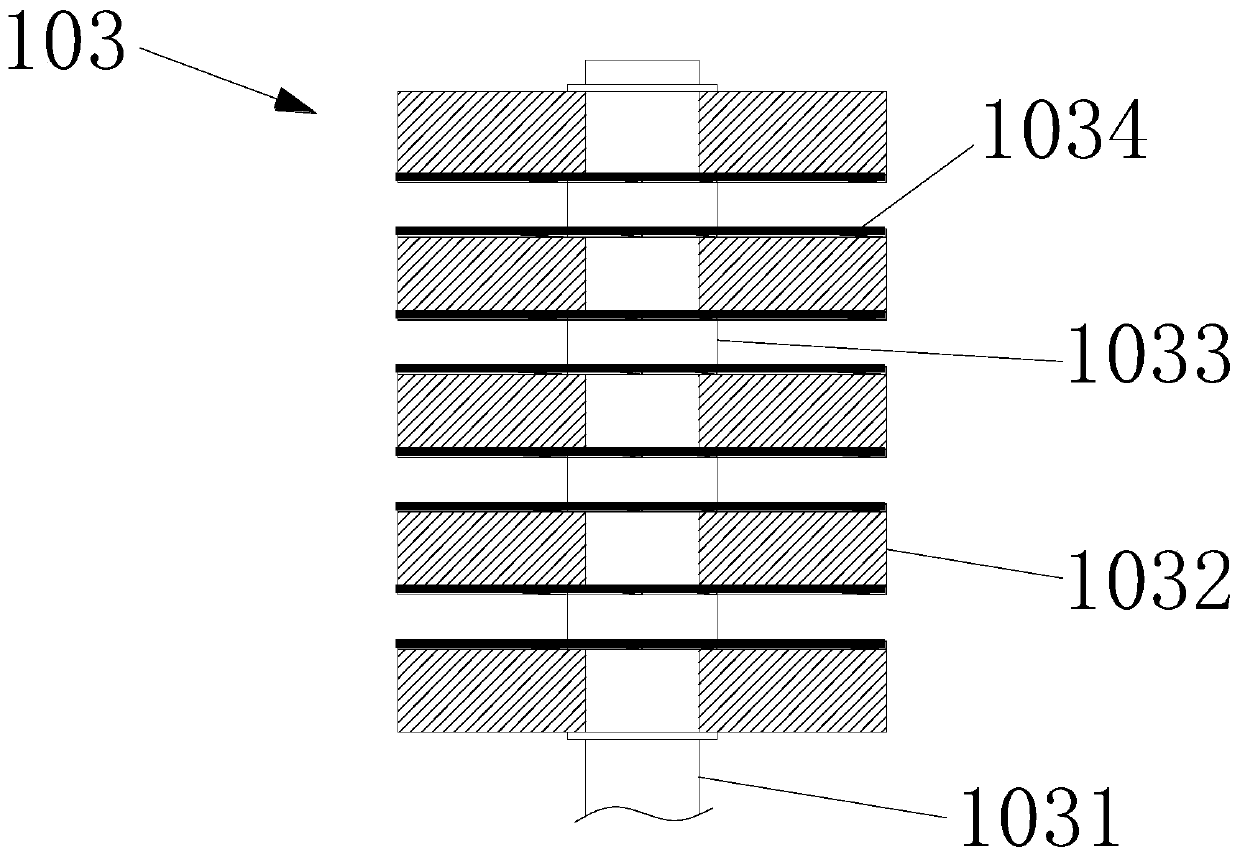
[0044] The first section 10 includes a feed channel 101 and a first cavity 102, the feed channel 101 is connected to the top of the first cavity 102 and is inclined, the top of the feed channel 101 has a feed port 1011, and A squeeze roller 103 for extruding plastic is installed in the material channel 101, and a magnet is arranged on the squeeze roller 103 to absorb ferromagnetic substances. The first cavity 102 is successively equipped with coarse crushing rollers according to the moving direction of the material. roller 104 and fine crushing roller 105.

[0045] The second section 20 includes a second cavity 201 , a shaft cylinder 202 axially disposed in the second cavity 201 , a helical blade 203 wound around the out...

Embodiment 2

[0058] This embodiment provides a method for integrated crushing and landfilling of plastic waste. When implementing the method, the landfill pit 70 is dug in advance, and the geotextile 80 is suspended and fixed in the landfill pit 70 (see Figure 8 ), then follow these steps:

[0059] In the first step, the plastic waste is crushed by using the plastic waste crushing device described in Example 1;

[0060] In the second step, the plastic waste after the first step is crushed is introduced into the waste conveying pipeline 60 (see figure 1 );

[0061] In the third step, feed running water into the garbage delivery pipeline 60, flush the plastic garbage into the pre-dug garbage landfill pit 70, and make the garbage and running water drop to the top of the geotextile 80 (see figure 1 and Figure 8 );

[0062] The 4th step, treat that the tap water on the geotextile 80 drips to the bottom of the landfill pit 70 and is drained away by the drainage pipe 90 at the bottom of the...

Embodiment 3

[0067] Based on Embodiment 1 and Embodiment 2, this embodiment provides a plastic waste disposal system, which includes a crushing device, a deflector 50 , a waste conveying pipeline 60 , a waste landfill pit 70 and a geotextile 80 .

[0068] The crushing device includes a first section 10, a second section 20, a third section 30, and a fourth section 40 in which the shells are connected in sequence; the first section 10 includes a feeding channel 101 and a first cavity 102, so The feed channel 101 is positioned above the first cavity 102 and is inclined. The top of the feed channel 101 has a feed port 1011. A squeeze roller 103 for extruding plastic is installed in the feed channel 101. The squeeze roll 103 A magnet is arranged on it to absorb ferromagnetic substances. The first cavity 102 is provided with a coarse crushing roller 104 and a fine crushing roller 105 successively according to the moving direction of the material; the second section 20 includes the second cavity ...


PUM


Abstract

The invention discloses a plastic garbage crushing device. The plastic garbage crushing device comprises four sections, wherein shells of the four sections are sequentially connected. The first section comprises a feeding channel provided with an extrusion roller and a first cavity provided with coarse and fine crushing rollers. The second section comprises a second cavity, a shaft barrel, spiralblades wound outside the shaft barrel and a first motor, wherein the shaft barrel is suspended and rotatably installed in the second cavity, and the rotation of the shaft barrel is driven by the firstmotor. The third section comprises a third cavity, a first crushing cutter and a second crushing cutter, wherein a plurality of arc-shaped openings are formed in two sides of the third cavity, and slicers on the first crushing cutter and the second crushing cutter can be cut into the arc-shaped openings to cut and crush plastic. The fourth section comprises a fourth cavity and a final crushing roller positioned in the fourth cavity, wherein the wall surface of the lower side of the fourth cavity is a mesh wall surface. The wall surfaces at the bottoms of the first cavity and the second cavityare both hole-type wall surfaces allowing water to penetrate through. On the one hand, plastic garbage can be crushed into extremely small particles, and on the other hand, the liquid in the plasticgarbage can be separated.

Description

technical field [0001] The invention relates to the field of garbage treatment, in particular to plastic garbage shredding treatment. Background technique [0002] At present, plastic waste is disposed of in the following ways in most countries: landfill, incineration and pyrolysis. Although the above disposal methods will inevitably have an impact on the environment, landfill and incineration will still be the most important disposal methods until a more reasonable and large-scale disposal method is found. [0003] At present, when plastic waste is landfilled in China, it is usually directly landfilled, and crushing devices are rarely used to crush plastic waste before landfilling. Moreover, although some plastic waste crushing devices have also appeared on the market at present, these crushing devices generally have the following disadvantages: (1) plastic waste is usually mixed with a large amount of liquid, and the existing crushing devices cannot effectively crush the ...

Claims


Application Information

Patent Timeline
Patent Type & Authority Applications(China)
IPC IPC(8): B02C21/00B02C23/02B02C4/00B02C4/08B02C18/14B02C18/18B02C23/16B03C1/10B30B9/12
CPCB02C4/00B02C4/08B02C18/14B02C18/18B02C21/00B02C23/02B02C23/16B02C2023/165B03C1/10B30B9/12
Inventor 何淑会
Owner 江苏伟曜塑胶科技有限公司
Why Eureka
Try Eureka