Novel permanent magnet brushless bench drill

A technology of permanent magnet brushless and bench drilling, which is applied in the direction of boring/drilling, large fixed members, drilling/drilling equipment, etc. It can solve the problems of power grid quality factor decline, aggravated power grid load, motor impact, etc., to achieve The effect of improving the quality factor, improving the efficiency of the whole machine and prolonging the service life

Active Publication Date: 2019-07-02
福建微龙电子科技有限公司
View PDF7 Cites 2 Cited by
  • Summary
  • Abstract
  • Description
  • Claims
  • Application Information

AI Technical Summary

Problems solved by technology

In addition, when the starting current is too large, the motor itself will be impacted by excessive electric force. If it is started frequently, there is a danger of overheating the winding.
Therefore, the starting design of asynchronous motors often faces a dilemma
[0005] 3. When the asynchronous motor is working, the rotor winding has current flowing, and this current is completely consumed in the form of heat energy, so a large amount of heat will be generated in the rotor winding, which will increase the temperature of the motor and affect the service life of the motor
[0006] 4. Due to the low power factor of the asynchronous motor, the motor has to absorb a large amount of reactive current from the power grid, resulting in a large amount of reactive current in the power grid, substation equipment and power generation equipment, which in turn reduces the quality factor of the power grid and aggravates the power grid. And gun substation equipment and power generation equipment load
At the same time, reactive current consumes part of the electric energy in the power grid, substation equipment and power generation equipment, resulting in low efficiency of the power grid and affecting the effective use of electric energy
Also due to the low efficiency of asynchronous motors, to meet the output power requirements, it is necessary to absorb more electric energy from the grid, which further increases the loss of electrical energy and increases the load on the grid
[0007] 5. The speed change of the drill floor is realized through the "tower pulley", which can only achieve a limited number of speed adjustments, and the single function greatly limits the use of the bench drill
[0008] 6. Traditional bench drills are generally only equipped with a fixed workpiece clamping table, and the traditional workpiece clamping table can only achieve simple lifting adjustment. If the actual workpiece needs to be drilled on multiple lateral slopes of the workpiece, the operation is difficult.

Method used


Image

  • Novel permanent magnet brushless bench drill
  • Novel permanent magnet brushless bench drill
  • Novel permanent magnet brushless bench drill

Examples


Embodiment 1

[0046] The present invention is a new type of permanent magnet brushless bench drill, and its use method can be carried out in the following steps: The present invention is a new type of permanent magnet brushless bench drill. "Tower pulley" transmission mechanism; the use of permanent magnet brushless motor has the following advantages:

[0047] 1. After the permanent magnet is embedded in the rotor of the permanent magnet synchronous motor, the rotor magnetic field is established by the permanent magnet. During normal operation, the rotor and the stator magnetic field run synchronously. There is no induced current in the rotor, and there is no rotor resistance loss. This is the only item It can improve the motor efficiency by 4% to 50%. Since there is no induction current excitation in the rotor of the hydromagnetic motor, the stator winding may be a purely resistive load, so that the power factor of the motor is almost 1, and the motor has a wide range of applications and a...

Embodiment 2

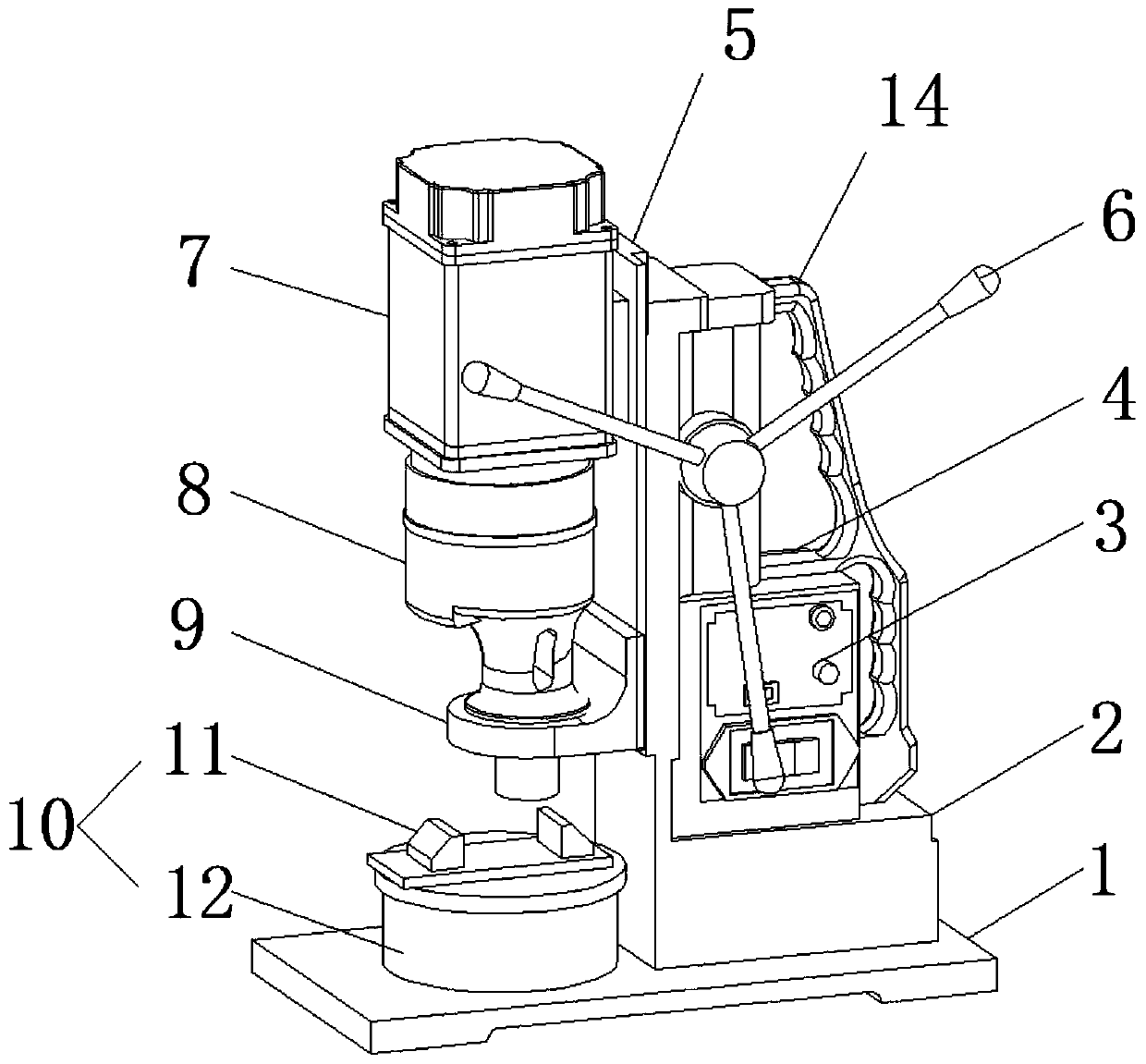
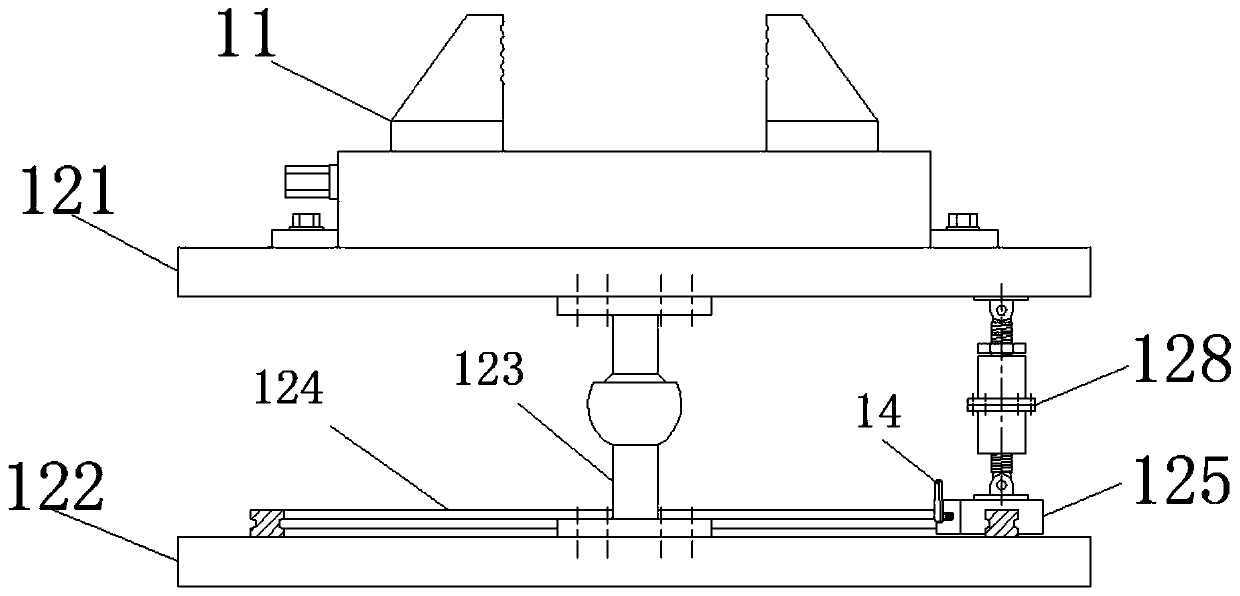
[0053] The top front side of the bench drill base plate 1 of the present invention is provided with a universal clamping table 10 for clamping and processing workpieces, and the universal clamping table 10 includes a bench vice 11 and a universal adjustment mechanism arranged at the bottom of the bench vice 11 12. Through the universal adjustment mechanism 12, corresponding adjustments can be made according to the special positional relationship between the required processing surface and the workpiece mounting surface, which can effectively reduce the difficulty of workpiece clamping and processing.

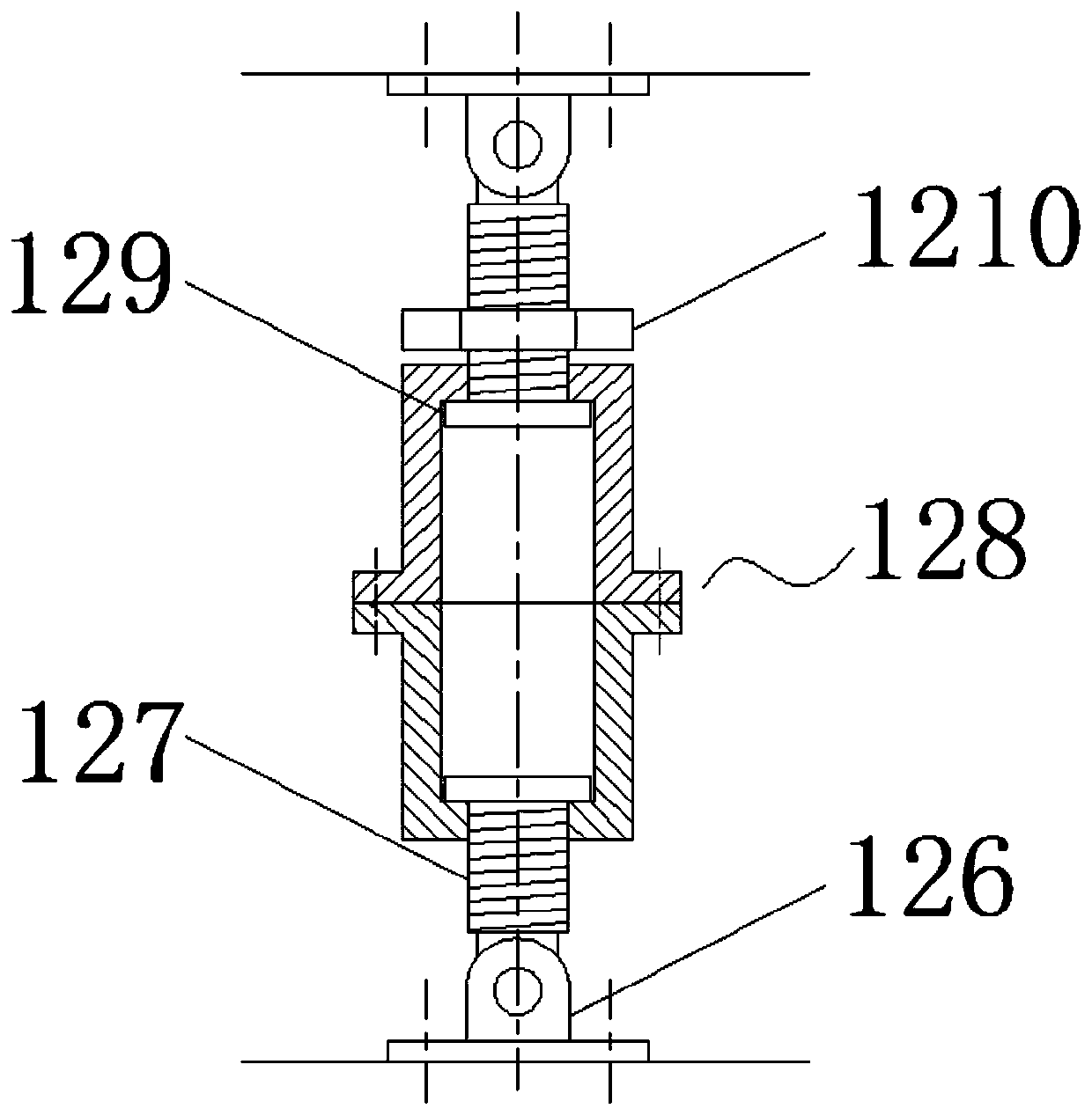
[0054] Specifically, when adjusting the inclination angle of the bench vise 11 and the upper fixing plate 121, first loosen the lock nut 1210, and then rotate the connecting sleeve 128. Adjust the total length of the screw rod 127 so that the upper fixed plate 121 can rotate a certain angle around the universal ball hinge on the adjustable support column 123 to realize the effect...


PUM


Abstract

The invention discloses a novel permanent magnet brushless bench drill, and belongs to the technical field of bench drills. The novel permanent magnet brushless bench drill comprises a bench drill bottom plate, wherein a machine body base is fixedly arranged on the rear side of the top of the bench drill bottom plate, a machine body shell is arranged at the top of the machine body base, a controlpanel for starting and stopping speed regulation is embedded below the side surface of the machine body shell, a lifting sliding table is arranged on the front side wall of the machine body shell, a main shaft lifting handle is arranged above the side surface of the machine body shell, and a permanent magnet brushless motor is fixedly arranged at the upper end of the front side wall of the liftingsliding table; and the bottom power output end of the permanent magnet brushless motor is connected with a bench drill main shaft, a main shaft mounting seat is fixedly arranged at the lower end of the front side wall of the lifting sliding table, a universal clamping table for clamping and machining workpieces is arranged on the front side of the top of the bench drill bottom plate, the universal clamping table is positioned directly below the bench drill main shaft, and the universal clamping table comprises a bench vice and a universal adjusting mechanism arranged at the bottom of the bench vice. The novel permanent magnet brushless bench drill is more energy-saving, efficient, convenient and practical.

Description

technical field [0001] The invention relates to the technical field of bench drills, in particular to a novel permanent magnet brushless bench drill. Background technique [0002] The bench drilling machine is referred to as a bench drill for short. It is a small drilling machine tool that is small in size and easy to operate. It is usually installed on a special workbench. Traditional bench drills generally use AC asynchronous motors as power motors, which are transmitted through tower pulleys so that traditional bench drills have the following shortcomings: [0003] 1. The work of the asynchronous motor is that the rotor winding needs to absorb part of the electric energy from the power grid for excitation, which consumes the power of the power grid. This part of the electric energy is finally consumed by current in the rotor winding. This loss accounts for about 20-30% of the total loss of the motor. It makes The efficiency of the motor is reduced, and the rotor excitati...

Claims


Application Information

Patent Timeline
Patent Type & Authority Applications(China)
IPC IPC(8): B23B39/00B23B47/06B23Q1/26
CPCB23B39/00B23Q1/26B23Q5/10
Inventor 林建辉曾信钿
Owner 福建微龙电子科技有限公司
Why Eureka
Try Eureka