Copper foil cutting machine

A cutting machine and copper foil technology, applied in metal processing, winding strips, thin material processing, etc., can solve problems such as copper foil damage, jamming, copper foil feeding problems, etc., to reduce quantity and reduce precision Requirements and eliminate stuck effects

Pending Publication Date: 2019-07-02
四川恒诚信电子科技有限公司
View PDF0 Cites 10 Cited by
  • Summary
  • Abstract
  • Description
  • Claims
  • Application Information

AI Technical Summary

Problems solved by technology

[0008] The invention provides a copper foil cutting machine, which solves the problem of excessive unwinding of the copper foil winding shaft of the existing copper foil cutting machine by eliminating excessive copper foil unwinding and flattening the copper foil before cutting In some cases, increasing the guiding precision of the copper foil by increasing the structure of the guiding copper foil winding shaft will increase the risk of the copper foil feeding being unsmooth or even stuck and eventually causing the copper foil to be damaged

Method used


Image

  • Copper foil cutting machine
  • Copper foil cutting machine
  • Copper foil cutting machine

Examples


Embodiment

[0038] Here, a preferred embodiment is used to illustrate the copper foil flattening mechanism 3 in the technical solution and a preferred copper foil cutting machine to which it can be applied.

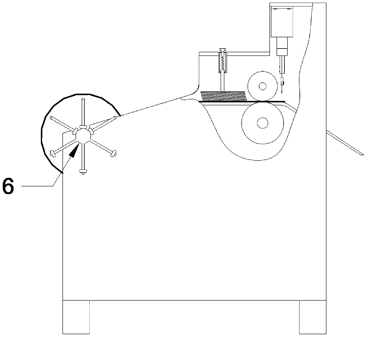
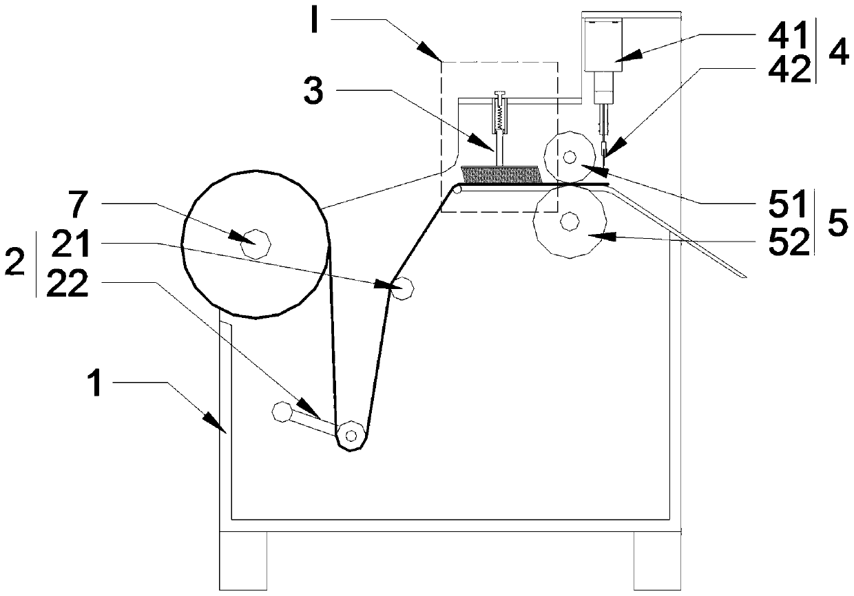
[0039] Similar to common copper foil cutting machines, the copper foil cutting machine in this embodiment includes a frame 1 for installing various components. The frame 1 can be a steel frame structure, which is welded to form a frame structure, and an installation location is reserved according to the arrangement of other components. Such as figure 1As shown, the frame 1 adopts a box structure, which is welded by 1-3mm steel plates to form the shape shown in the figure, so as to improve the integrity and aesthetics of the entire cutting machine; at the same time, because the side adopts a closed structure, it can also Improve the safety performance of the cutting machine. The tail of the frame 1 is in the shape of two steps rising in sequence, and a cutting mechanism 4 with a dow...

Embodiment 2

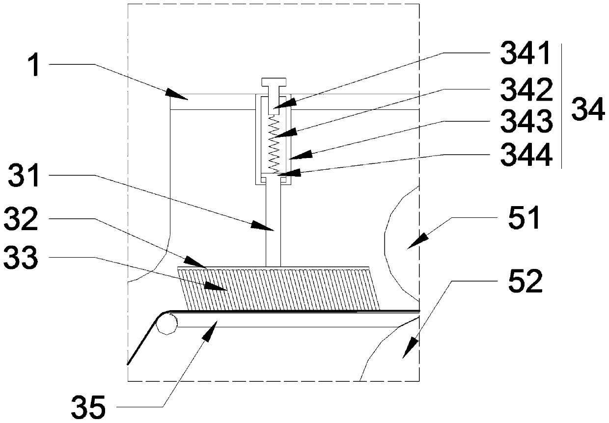
[0060] Since the copper foil has multiple thickness specifications, and the distance between the flattening mechanism and the feeding plate 35 in Embodiment 1 is fixed, the pressures that copper foils of different thicknesses are subjected to under the flattening mechanism are different, and the final flattening effect obtained by it is different. Effects also vary. Therefore, based on Embodiment 1, this embodiment provides a flattening mechanism with adjustable pressure generated by soft contact with the copper foil or the feeding plate 35 .

[0061]The difference between this flattening mechanism and the flattening mechanism in Embodiment 1 is that the fixed rod 31 of the flattened mechanism in Embodiment 1 is directly fixedly connected with the frame 1, while in the flattened mechanism in this embodiment, the fixed rod 31 is fixedly connected with the frame 1 through a piston structure 34 with adjustable damping size. The specific structure of a preferred solution of this ...


PUM


Abstract

The invention relates to a copper foil cutting machine. The copper foil cutting machine comprises a rack, a cutting mechanism mounted on the head of the rack, a copper foil conveying mechanism mountedon the rack and located behind the cutting mechanism, a guiding mechanism mounted on the rack and located behind the copper foil conveying mechanism, and a copper foil winding shaft mounted at the tail of the rack; a copper foil flattening mechanism used for spreading and flattening copper foil before the copper foil enters the conveying mechanism is arranged between the copper foil conveying mechanism and the guiding mechanism; and an inertia buffer mechanism used for weakening inertia rotation of the copper foil winding shaft is arranged at the end of the foil shaft winding shaft. Through the copper foil flattening mechanism, the copper foil can be flat spread before entering the conveying device, meanwhile, through cooperation with the inertia buffer mechanism, excessive unwinding of the copper foil is limited, tensioning and accurate guiding under guiding of a non-clamping-type guiding mechanism composed of a tension roller and a single-level guide roller are achieved, thus it iseffectively ensured that the copper foil can flat enter the copper foil conveying mechanism in the forward direction at any time, and the possibility that the copper foil is folded and damaged is eliminated.

Description

technical field [0001] The invention relates to the technical field of copper foil cutting, in particular to a copper foil cutting machine. Background technique [0002] Copper foil, especially electronic-grade copper foil, is one of the important basic materials of the electronics industry. With the rapid development of the electronic information industry, its usage is increasing and its application fields are becoming wider and wider. Among them, the amount of copper foil used in printed circuit boards and lithium-ion batteries is the largest. [0003] Copper foil usually needs to be trimmed before further processing of other finished parts to obtain copper foil blocks with appropriate dimensions. Generally, a loading and cutting machine is used to cut the copper foil. [0004] The existing copper foil cutting machine generally includes a copper foil winding shaft for providing copper foil raw materials, a guiding mechanism for guiding the copper foil direction, a cuttin...

Claims


Application Information

Patent Timeline
Patent Type & Authority Applications(China)
IPC IPC(8): B26D7/14B65H23/26B65H23/34
CPCB26D7/14B65H23/26B65H23/34
Inventor 田云杰匡卿谊
Owner 四川恒诚信电子科技有限公司
Why Eureka
Try Eureka