A dust-proof self-cleaning combined self-draining permeable brick
A technology of self-cleaning and permeable bricks, applied in roads, buildings, side ditches/curbs, etc., can solve problems such as clogging of permeable pores, and achieve the effects of pressure relief, good permeability and strong adjustment ability
- Summary
- Abstract
- Description
- Claims
- Application Information
AI Technical Summary
Problems solved by technology
Method used
Image

Examples
Embodiment 1
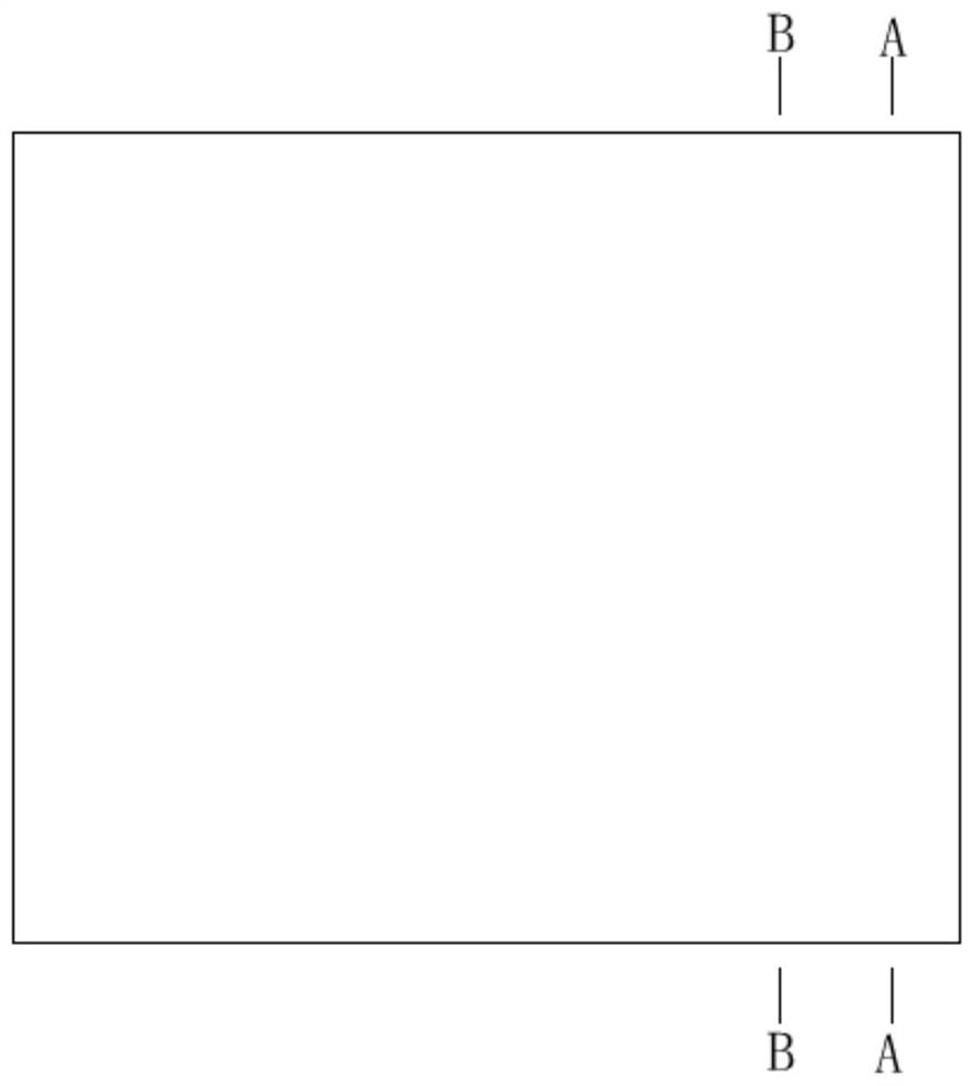
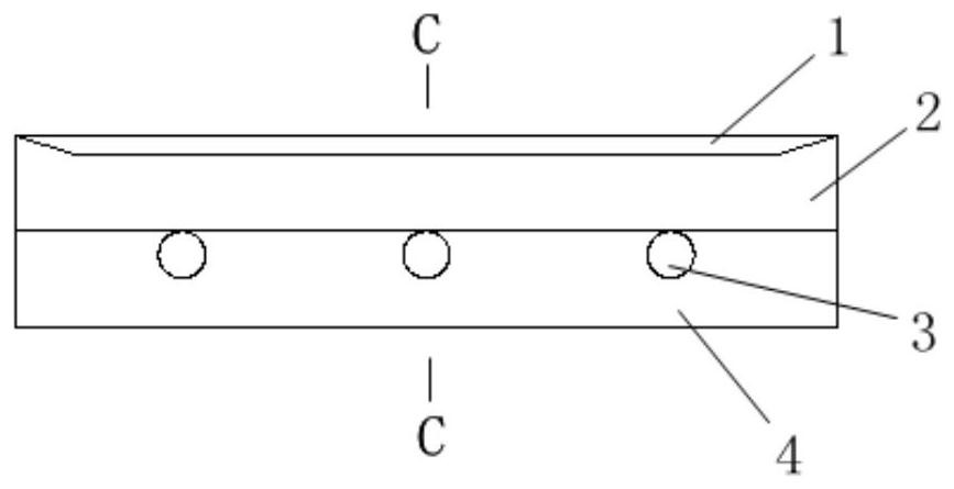
[0027] Such as Figure 1-4 As shown, the permeable brick structure of the present invention includes: a silica sand permeable layer 1 composed of aggregate particles and a hydrophilic binder covering aggregate, and a silica sand permeable layer 1 composed of aggregate particles and a binder covering aggregate The sand-free concrete water-permeable layer 2, and the water-guiding channels 5 (three are shown in the figure, but other numbers can also be used) are provided through the concrete bottom layer 4 .
[0028] Wherein, the sand-free concrete permeable layer 2 is located below the silica sand permeable surface layer 1 and combined with the silica sand permeable surface layer 1 . Preferably, the thickness of the silica sand water-permeable layer 1 is 1.5-3 cm, and the thickness of the sand-free concrete water-permeable layer 2 is 4-6 cm. Wherein, the aggregate particle size contained in the silica sand water-permeable layer 1 is relatively small, and the particle size is si...
Embodiment 2
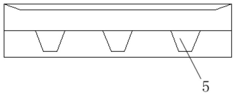
[0045] Figure 5 Shown is the permeable brick of Embodiment 2 of the present invention, which is basically the same as Embodiment 1, except that the structure of the main body 41 and the blocking portion 42 of the concrete bottom layer 4, specifically, the main body 41 and the blocking portion 42 is an arc-shaped connection structure, the inner surface of the blocking portion 42 is an inclined structure, and the connection between the inner surface and the upper end of the blocking portion 42 is also a circular arc transition. Wherein, preferably, the radius of curvature of the arc-shaped connecting portion is 10-20 mm, the inclination of the inclined structure is 5-10 degrees, and the radius of curvature of the arc transition is 5-10 mm.
[0046] With such a structure, when the rainwater flows through the blocking portion 42, it is smoother, and the effect of scouring sand and soil is better.
Embodiment 3
[0048] Figure 6-7 , shows the permeable brick of Example 3, wherein, the bottom surface of the sandless concrete permeable layer 2 is provided with an impermeable water-retaining layer 21, and the water-retaining layer 21 is arranged on the side of the outlet end, and is in the form of The slope is arranged so that rainwater can flow from the right to the left in the figure. More preferably, at least part of the gap exists between the water-retaining layer 21 and the sand-free concrete water-permeable layer 2 to facilitate the circulation of rainwater.
[0049] With such a structure, rainwater can be concentrated toward the side of the inlet 6, so that the water collected on the inlet side is more concentrated, and the scouring force generated to the right is more obvious.
[0050] In another preferred solution, the water-retaining layer 21 is a wave-shaped structure (such as roof tiles), and gaps are formed at some positions at the top of the wave, so that rainwater can dir...
PUM
 Abstract
Description
Claims
Application Information
 - R&D
- Intellectual Property
- Life Sciences
- Materials
- Tech Scout
- Unparalleled Data Quality
- Higher Quality Content
- 60% Fewer Hallucinations
Browse by: Latest US Patents, China's latest patents, Technical Efficacy Thesaurus, Application Domain, Technology Topic, Popular Technical Reports.
© 2025 PatSnap. All rights reserved.Legal|Privacy policy|Modern Slavery Act Transparency Statement|Sitemap|About US| Contact US: help@patsnap.com