Temperature detecting circuit and implanted medical device using the same

A temperature detection circuit and circuit technology, applied in the direction of adjusting electrical variables, control/regulation systems, instruments, etc., can solve the problems of damaging human tissue, increasing battery burden, unfavorable implantation devices, etc.

Pending Publication Date: 2019-07-02
SCENERAY
View PDF0 Cites 1 Cited by
  • Summary
  • Abstract
  • Description
  • Claims
  • Application Information

AI Technical Summary

Problems solved by technology

[0005] The electric energy of wireless charging will lose energy during the transmission process, and part of the energy will be released in the form of heat energy. The problem is that the temperature of the part where the human body is implanted with the stimulator will increase.
If the temperature continues to increase and exceeds a certain value of the human body temperature, the human body will feel uncomfortable, and in extreme cases, it may damage human tissue; in order to realize temperature monitoring, in the prior art, a thermistor is generally integrated in the PCB as a temperature detection, but due to The thermistor has a large error and is easy to absorb current, which reduces the accuracy of temperature monitoring and increases the burden on the battery. As an external device, the thermistor may be easily damaged by the device and occupies a large space, which is not conducive to Make smaller implants

Method used


Image

  • Temperature detecting circuit and implanted medical device using the same
  • Temperature detecting circuit and implanted medical device using the same
  • Temperature detecting circuit and implanted medical device using the same

Examples


specific Embodiment

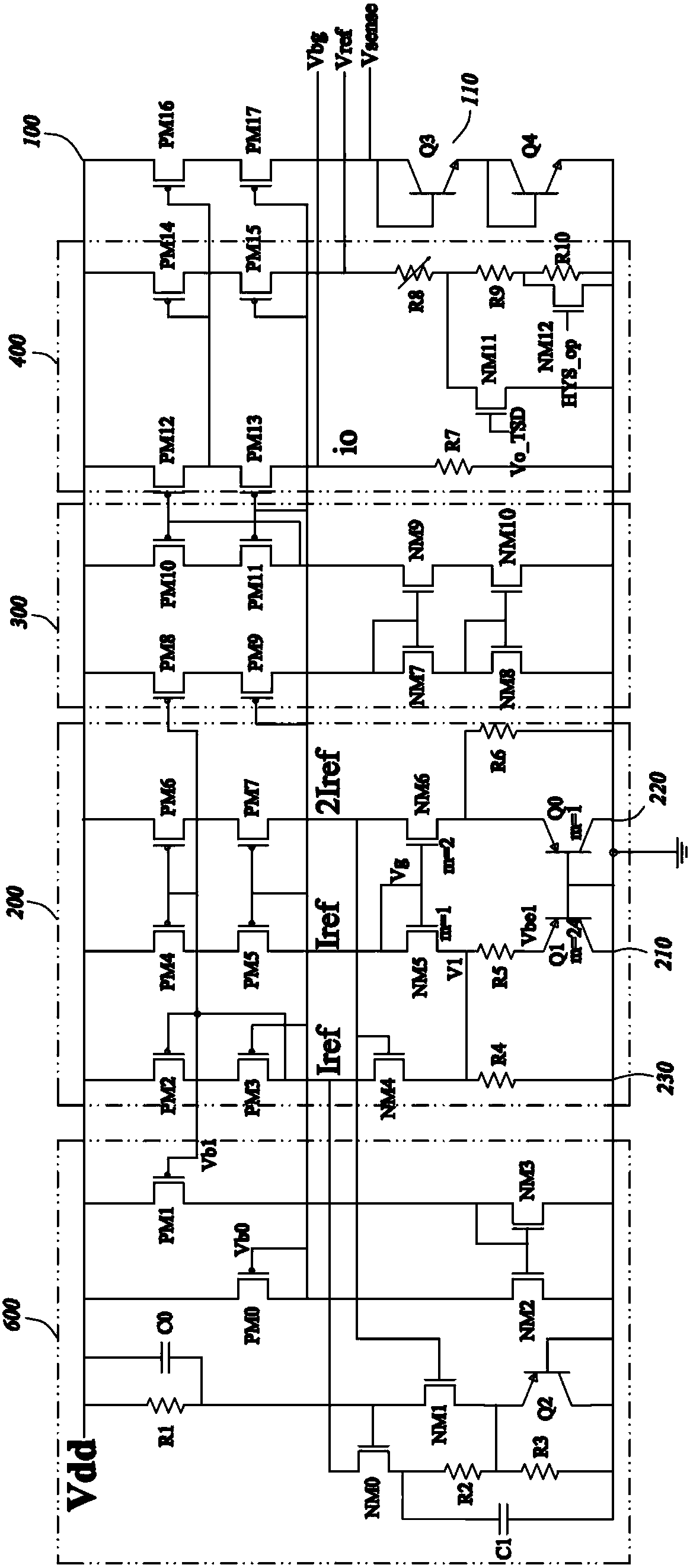
[0036] The invention provides an implantable medical device and a temperature detection circuit in an integrated circuit thereof.

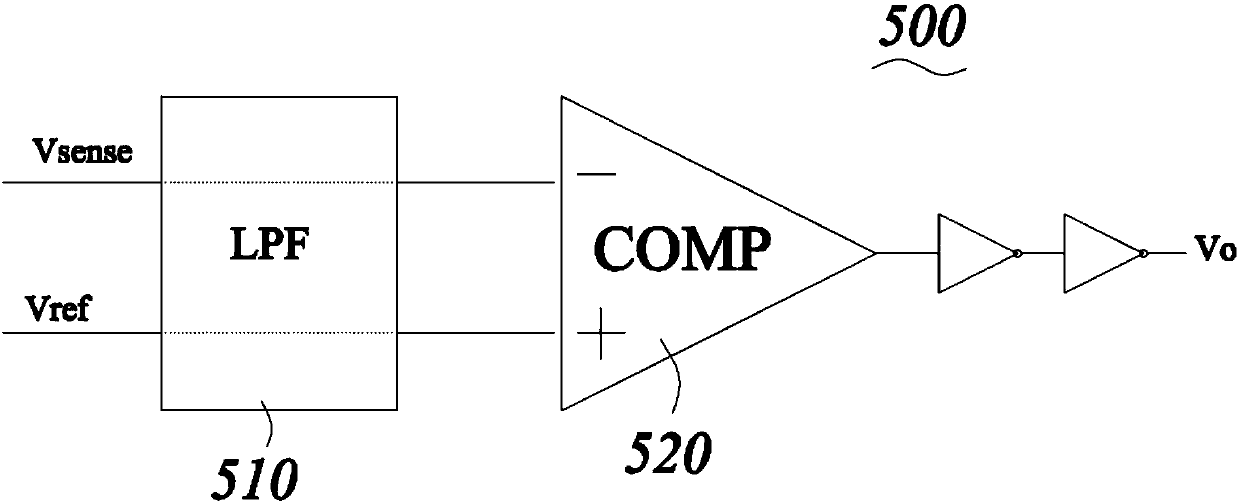
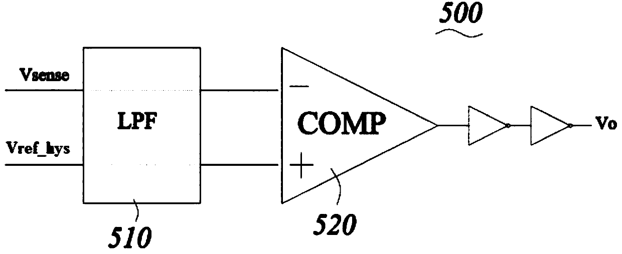
[0037] Specifically, see figure 1 with figure 2As shown, the temperature detection circuit proposed by the present invention includes a temperature sensing circuit 100 for obtaining a temperature voltage Vsense, a reference current generating circuit 200 for generating a reference current Iref, a trimming circuit 300 for generating a trimming current Io, and a generating reference voltage Vbg The voltage generation circuit 400 for the threshold voltage Vref and the comparison circuit 500 for comparing the voltage value of the temperature voltage Vsense with the threshold voltage Vref, if the temperature voltage Vsense is greater than the threshold voltage Vref, then output the first control signal Vo1, if the temperature voltage Vsense is less than or equal to the threshold voltage Vref, then the second control signal Vo2 is output.

[0038] co...


PUM


Abstract

The invention discloses a temperature detecting circuit comprising a temperature sensing circuit for acquiring a temperature voltage, a reference current generating circuit for acquiring a reference current with a temperature coefficient of zero, a trimming circuit for carrying out proportion-based mirror image trimming on the reference current to obtain a trimming current, a voltage generating circuit for generating a quasi-voltage and a threshold voltage corresponding to a first threshold temperature, and a comparing circuit. The comparing circuit is used for comparing the temperature voltage with the threshold voltage, outputting a first control signal when the temperature voltage is greater than the threshold voltage, and outputting a second control signal if the temperature voltage isless than or equal to the threshold voltage. According to the temperature detecting circuit provided by the invention, after generation of the reference current with the adjustable temperature coefficient, the trimming circuit and the voltage generating circuit are used for carrying out proportion-based mirror imaging on the reference current to a reference voltage circuit and a threshold voltagecircuit so as to generate a reference voltage and a threshold voltage that are not affected by the temperature change. Therefore, the comparison result of the comparison circuit is more accurate andpower consumption of the entire circuit is also reduced.

Description

technical field [0001] The invention belongs to the field of implantable medical devices, in particular to a temperature detection circuit and an implantable medical device using the same. Background technique [0002] In implantable medical devices, nerve stimulators can effectively control the symptoms of functional neurological diseases and mental diseases by chronically stimulating target nerves. Common implantable medical devices are used to treat cardiac arrhythmia pacemakers, defibrillators to treat heart fibrillation, retinal stimulators to treat blindness, muscle stimulators to produce coordinated limb movements, and more. [0003] Generally speaking, the components of an implantable neurostimulator include a stimulation chip, a stimulation controller, a wireless communication module, a voltage conversion module, a wireless charging module, a battery, and so on. Implantable neurostimulators consume power during normal operation, and the more functions they have, th...

Claims


Application Information

Patent Timeline
Patent Type & Authority Applications(China)
IPC IPC(8): G05F1/567
CPCG05F1/567
Inventor 颜雨陈方雄
Owner SCENERAY
Why Eureka
Try Eureka