
Waste centrifugal extractor

A centrifugal extractor and waste technology, which is applied in solvent extraction, liquid solution solvent extraction, separation methods, etc., can solve the problems of insufficient mixing and separation effect of light and heavy phases, vibration of centrifugal extractor, and limitation of rotating drum speed, etc. Improve mixing and separation effect, separate sufficient, reduce the effect of entrainment

Inactive Publication Date: 2019-07-05
YANGZHOU CHENGUANG SPECIAL EQUIP
View PDF7 Cites 2 Cited by
  • Summary
  • Abstract
  • Description
  • Claims
  • Application Information

AI Technical Summary

Problems solved by technology

Moreover, when the main shaft drives the drum at the end to rotate at high speed, it will cause the centrifugal extractor to vibrate. The higher the speed, the more serious the vibration, which limits the speed of the drum and makes the mixing and separation of light and heavy phases not good enough.

Method used


Image

  • Waste centrifugal extractor
  • Waste centrifugal extractor
  • Waste centrifugal extractor

Examples


Embodiment Construction

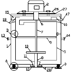
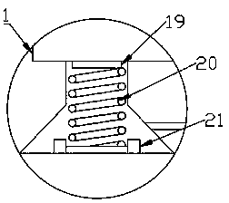
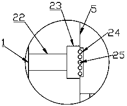
[0021] Such as figure 1 It is a structural schematic diagram of the present invention, a waste centrifugal extractor, including a casing 1, a centrifugal motor 2 is arranged on the top surface of the casing 1, a base 3 is arranged on the bottom surface of the casing 1, and a There is a shock absorbing device, a mixing tank 4 is arranged on the housing 1 between the bases 3, a drum 5 is arranged inside the housing 1, and a stabilizing device is arranged between the drum 5 and the housing 1, The drum 5 and the housing 1 are provided with a first transmission shaft 6 , a second transmission shaft 7 and a third transmission shaft 8 , and the second transmission shaft 7 is arranged on the first transmission shaft 6 and the third transmission shaft 8 Between, the other end of the first transmission shaft 6 passes through the top surface of the housing 1 and is connected to the centrifugal motor 2, the other end of the third transmission shaft 8 is rotationally connected to the botto...


PUM


Abstract

The invention relates to the technical field of garbage treatment equipment, and particularly relates to a waste centrifugal extractor. The waste centrifugal extractor comprises a shell; bases are arranged under the bottom surface of the shell; a damping device is arranged in each base; a mixing groove is formed in the shell among the bases; a rotary drum is arranged in the shell; a stabilizing device is arranged between the rotary drum and the shell; a first transmission shaft, a second transmission shaft and a third transmission shaft are arranged in the rotary drum and the shell; the otherend of the first transmission shaft penetrates through the top surface of the shell and is connected with a centrifugal motor; the other end of the third transmission shaft is rotationally connected with the bottom surface of the mixing groove; a hub is arranged at the middle of the second transmission shaft; a flow baffle plate is arranged at the joint of the second transmission shaft and the third transmission shaft; and an impeller and a vortex guide vane are sequentially arranged at the tail end of the third transmission shaft. Due to the damping device and the hub, vibration of the rotarydrum is reduced, so that the rotating speed of the rotary drum can be higher; the mixing groove, and the impeller and the vortex guide vane on the third transmission shaft are arranged on the bottomsurface of the shell, so that two-phase materials can be well mixed; and the flow baffle plate can reduce the liquid outlet speed of light phase liquid and heavy phase liquid.

Description

technical field [0001] The invention relates to the technical field of waste treatment equipment, in particular to a waste centrifugal extractor. Background technique [0002] The working process of the centrifugal extractor is mainly divided into two parts: the mixing mass transfer process and the centrifugal separation process. The two liquids to be mixed are mixed under the rotation of the drum or paddle of the centrifugal extractor. The liquid enters the drum and rotates at a high speed driven by the drum to generate centrifugal force. Under the action of centrifugal force, the liquid with high density gathers outward, and the liquid with low density gathers inward. The two liquids will gradually stratify to form an interface. The denser liquid on the outside exits the extractor through the heavy phase outlet, and the less dense liquid on the inside exits the extractor through the light phase outlet, thus completing the separation process. Moreover, when the main shaft ...

Claims


Application Information

Patent Timeline
IPC IPC(8): B01D11/04
CPCB01D11/0476
Inventor 沈吉兆夏永奎王铁军
Owner YANGZHOU CHENGUANG SPECIAL EQUIP
Learn More