Energy-saving type water purifying system

A water purification system and energy-saving technology, applied in the field of water purification, can solve problems such as increased cost and difficulty, and achieve the effect of good purification effect and simple structure design.

Pending Publication Date: 2019-07-05
HUBEI UNIV
View PDF0 Cites 2 Cited by
  • Summary
  • Abstract
  • Description
  • Claims
  • Application Information

AI Technical Summary

Problems solved by technology

[0004] However, the carbon fiber floating bed and the adsorption device can only contact the water below the floating bed to treat the water quality of a small volume of water. The gas device is beneficial to the aerobic reaction of microorganisms, so the cost and difficulty are greatly increased

Method used


Image

  • Energy-saving type water purifying system
  • Energy-saving type water purifying system
  • Energy-saving type water purifying system

Examples


Embodiment 1

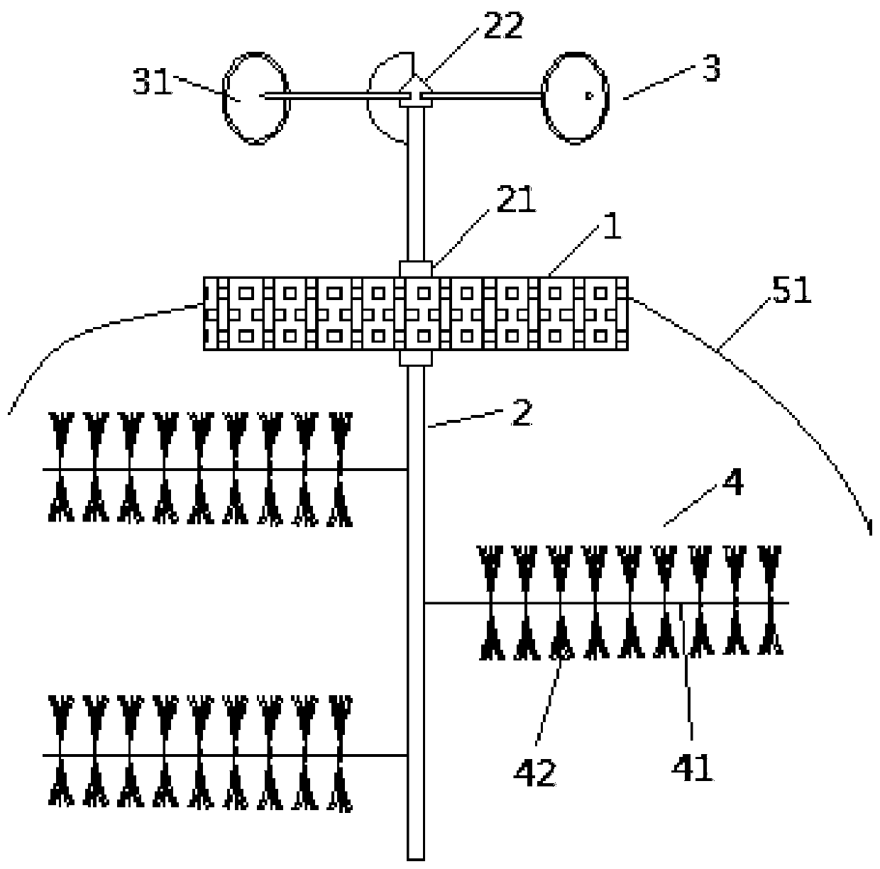
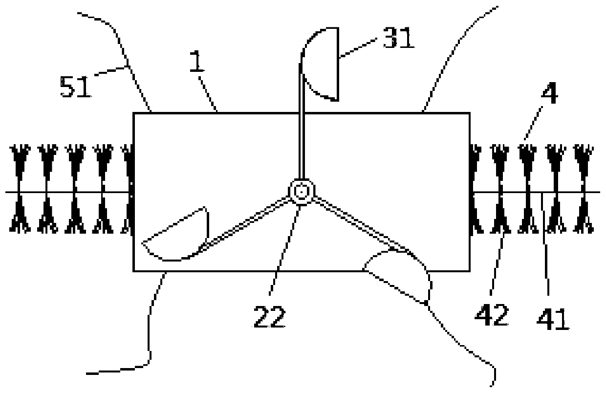
[0032] Embodiment one: if figure 1 and 2 As shown, the energy-saving water purification system of this embodiment includes a floating bed 1, which is used to float on the surface of a water body or in a water body; a rotating shaft 2, the above-mentioned rotating shaft 2 is vertically arranged, and its lower end runs through the above-mentioned floating bed 1 from top to bottom, and It is rotationally connected with the above-mentioned floating bed 1; the wind-driven structure 3, the above-mentioned wind-driven structure 3 is installed on the upper end of the above-mentioned rotating shaft 2, and is used to drive the above-mentioned rotating shaft 2 to rotate around its axis under the action of wind; the pollutant purification component 4, the above-mentioned pollutant purification The component 4 is installed at the lower end of the above-mentioned rotating shaft 2, and is used for purifying pollutants in the water body as the above-mentioned rotating shaft 2 rotates.

[003...

Embodiment 2

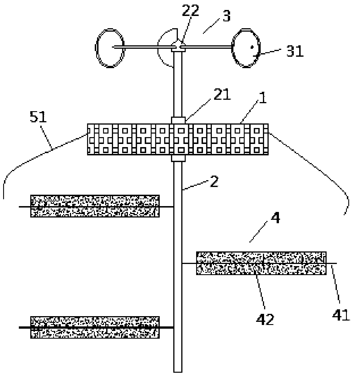
[0041] Embodiment two: if image 3 and 4 As shown, the above-mentioned pollutant purification units 42 are all solid adsorbent layers, and the above-mentioned adsorbent layers are wrapped and fixed on the outside of the support rod 41 along the length direction of the corresponding above-mentioned support rod 41, and the outside is wrapped with gauze. When there is wind, the wind force acts on the wind-driven structure 3, driving the wind-driven structure 3 to drive the rotating shaft 2 to rotate relative to the floating bed 1, thereby driving the pollutant purification assembly 4 at the lower end of the rotating shaft 2 to rotate, that is, the pollutant purification unit 42 ( Adsorbent layer) and the corresponding support rod 41 rotate with the rotating shaft 2, and the rotation of the adsorbent layer disturbs the water body to achieve the oxygenation effect, and the adsorbent layer can more fully contact the water body, and the pollutants in the water are removed by the adso...


PUM


Abstract

The invention belongs to the technical field of water purifying, and particularly relates to an energy-saving type water purifying system. The energy-saving type water purifying system comprises a floating bed, a connection rod, a wind power driving structure and a contaminant purifying assembly, wherein the floating bed is used for being floated on the surface of water or into the water; the connection rod is vertically arranged, and the lower end of the connection rod penetrates through the floating bed from top to bottom and is rotationally connected with the floating bed; the wind power driving structure is installed at the upper end of the connection rod, and used for driving the connection rod to rotate around the axis of the connection rod under the action of wind power; the contaminant purifying assembly is installed at the lower end of the connection rod, and used for purifying contaminants in the water along with rotation of the connection rod. The energy-saving type water purifying system has the advantages that the structural design is simple and reasonable, in the purifying process, the wind power is sufficiently utilized to serve as an energy source to drive the contaminant purifying assembly to rotate so as to purify the contaminants in the water, in the purifying process, the water can be disturbed, natural aeration of the water is achieved, and the purifying effect is good.

Description

technical field [0001] The invention belongs to the technical field of water purification, in particular to an energy-saving water purification system. Background technique [0002] With people's emphasis on ecological environment issues, the water quality of lakes and rivers has improved in recent years, and the treatment of polluted water bodies such as lakes, rivers and reservoirs has attracted more and more attention. There are three methods of restoration of water bodies: physical, chemical, and biological. Ecological technologies mainly include artificial wetlands, aeration and oxygenation, biofilm technology, and floating bed technology. Carbon fiber is currently the most widely used biofilm technology. The material has good biocompatibility, strong tensile strength, high fiber strength, durability, and long service life. It also has unique fast adsorption and desorption properties and Selective adsorption performance, often used in combination with artificial floati...

Claims


Application Information

Patent Timeline
IPC IPC(8): C02F3/34C02F3/30C02F3/10C02F9/14C02F7/00
CPCC02F3/34C02F3/301C02F3/106C02F7/00C02F9/00C02F1/28C02F2103/007Y02W10/10
Inventor 赵丽娅钟韩珊王敏齐开
Owner HUBEI UNIV
Why Eureka
Try Eureka