Air spinning machine

A technology of open-end spinning and drafting device, applied in spinning machine, continuous winding spinning machine, textile and paper making, etc., can solve the problems of fiber deviation, detachment from sliver, etc., to achieve uniformity and accurate parallel position , the effect of improving uniformity

Pending Publication Date: 2019-07-05
SAURER GERMANY GMBH & CO KG
View PDF10 Cites 3 Cited by
  • Summary
  • Abstract
  • Description
  • Claims
  • Application Information

AI Technical Summary

Problems solved by technology

The problem of fiber deviation and partial detachment from the sliver is thus not solved satisfactorily

Method used


Image

  • Air spinning machine
  • Air spinning machine
  • Air spinning machine

Examples


Embodiment Construction

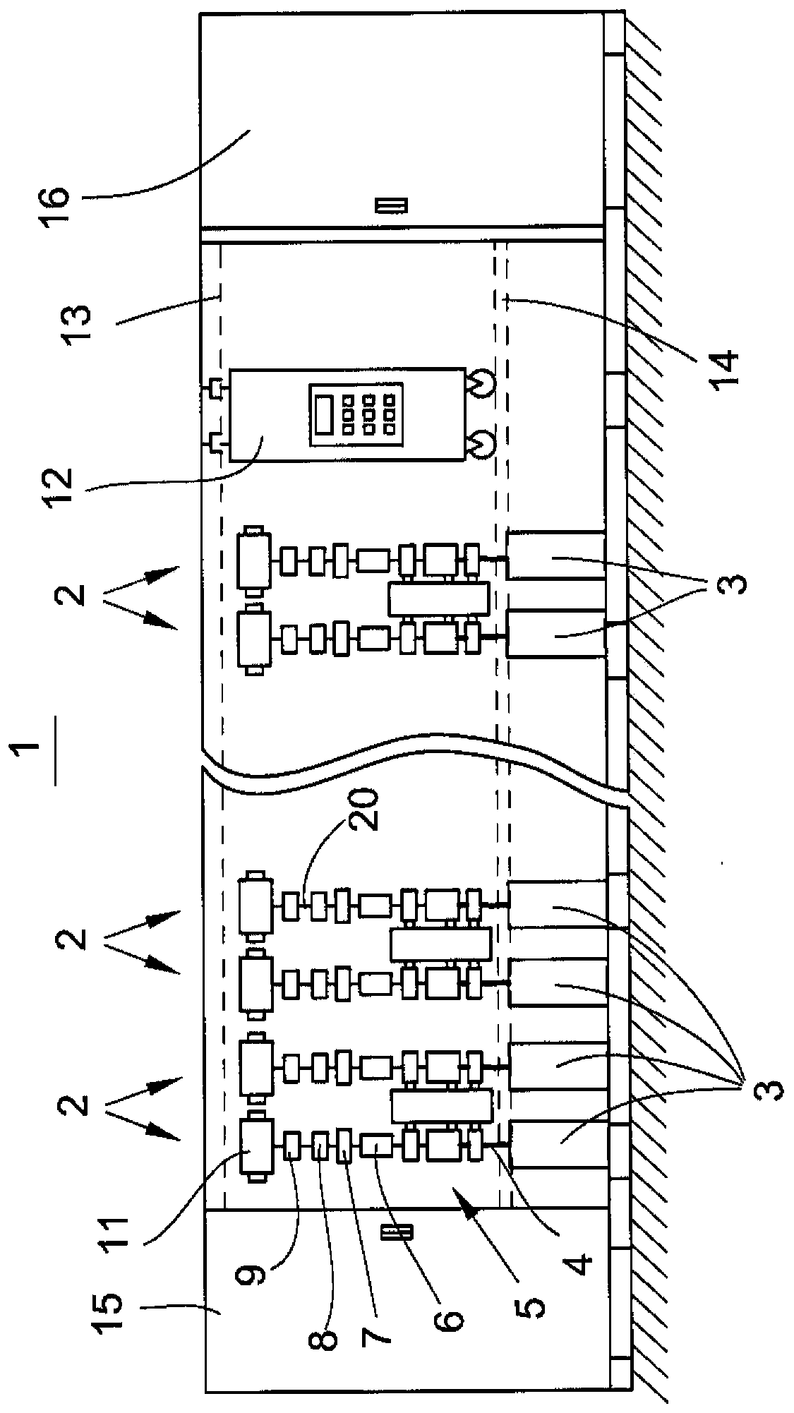
[0025] figure 1 A front view of the air spinning machine 1 is schematically shown. The textile machine has a plurality of work stations or spinning stations 2 arranged next to each other, which are positioned between so-called end frames 15 , 16 arranged on the end sides.

[0026] Such as figure 1 It is further shown that each station 2 is equipped with feed material, for example a sliver 4 stored in a spinning barrel 3 .

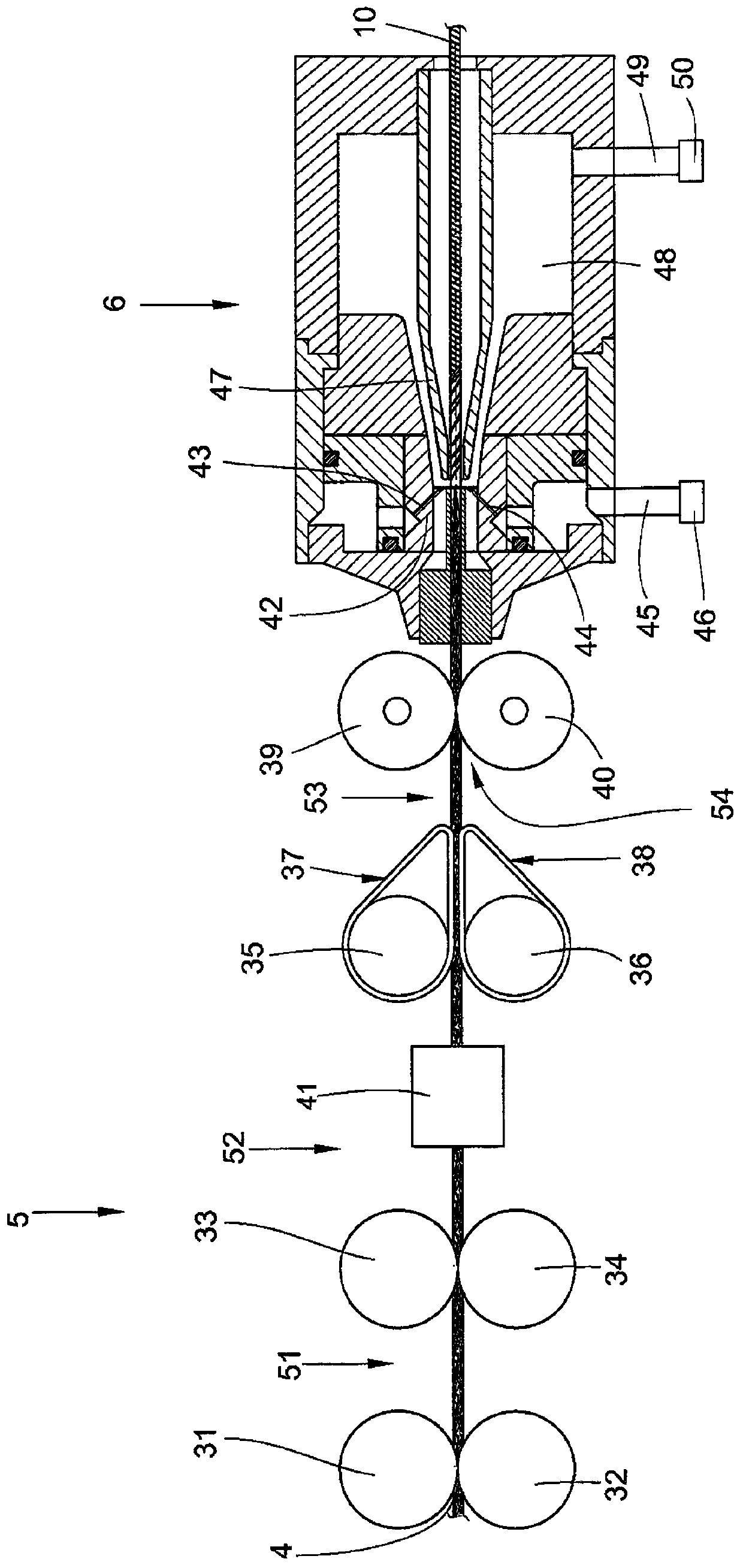
[0027] In addition, each station 2 also has a drafting device 5, an air spinning device 6, a yarn unwinding device 7, a yarn clearer 8 and a winding device.

[0028] The associated yarn traversing device 9 serves to wind the yarn 10 produced from the sliver 4 in the rotor spinning unit 6 onto the winding bobbin 11 in interdigitated layers.

[0029] The winding bobbin or cross-winding bobbin 11 is usually held on a creel (not shown) and is rotated by a bobbin drive (also not shown).

[0030] Such as figure 1 It is further shown that the workstation 2 of...


PUM


Abstract

The invention relates to an air spinning machine for producing yarn. The air spinning device has a fiber belt which is stretched by a stretching unit and is supplied to an air spinning equipment for generating a yarn twist, where the fiber belt is withdrawn from the air spinning equipment and is wound onto a cross-wound bobbin. Here, it is possible to minimize the occurrence of a yarn deflection,which is formed in particular by the airflow on the basis of the rotational speed of a stretching unit output roller. A false twisting unit is arranged in a pre-drafting zone of the stretching unit. The false twisting unit is granted with alternating direction of rotation of the fiber belt, before it is moved in the main drafting zone on yarn count and is supplied to the air spinning equipment.

Description

[0001] This application is a divisional application of an invention patent application with an international filing date of December 5, 2013, an application number of 201310757014.3, and an invention title of "air spinning device". technical field [0002] The invention relates to an air spinning device for producing yarn. In the air spinning device, a drafting device is used to draft a sliver, and then the sliver is delivered to an air spinning unit to generate twisting of the yarn. From the air spinning The spinning machine draws the sliver and winds it onto a cross-winding bobbin. Background technique [0003] Conventional textile methods established on the market, such as ring spinning, compact and rotor spinning, almost reach method-specific limits with regard to their productivity. In particular mechanical components for configuring the twist by using air in the original spinning process should be dispensed with and pneumatic devices used instead. [0004] For open-en...

Claims


Application Information

Patent Timeline
Patent Type & Authority Applications(China)
IPC IPC(8): D01H5/28
CPCD01H1/115D01H5/28
Inventor T·维德C·赛沙伊尔R·维尔纳
Owner SAURER GERMANY GMBH & CO KG
Why Eureka
Try Eureka