Automatic feeding assembly and washing machine
A technology of automatic feeding and components, which is applied in the field of washing machines, can solve the problems of high cost, unfavorable automatic feeding components, miniaturization and large size of washing machines, etc., and achieve the effect of simplifying components, facilitating miniaturization design, and simplifying structural design
- Summary
- Abstract
- Description
- Claims
- Application Information
AI Technical Summary
Problems solved by technology
Method used
Image
Examples
Embodiment 1
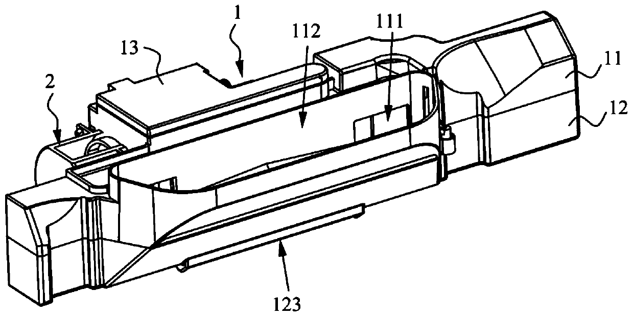
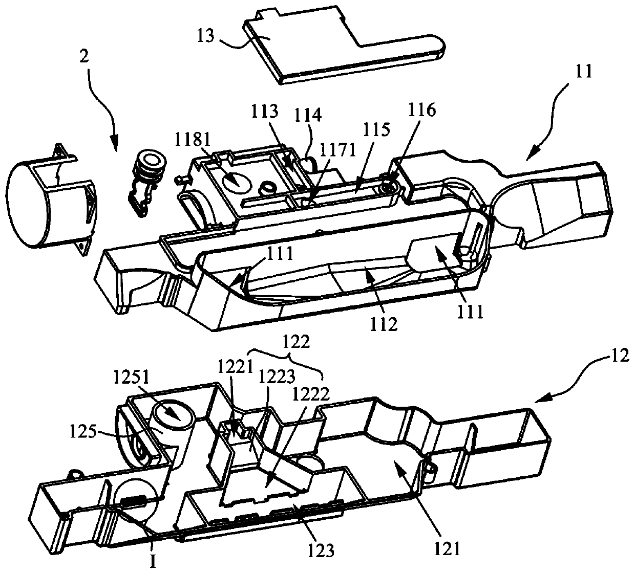
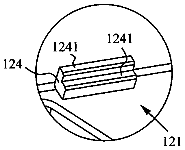
[0054] figure 1 It is a schematic structural diagram of the automatic delivery component provided by the embodiment of the present invention, figure 2 A schematic structural diagram of the split structure of the automatic delivery component provided by the embodiment of the present invention in the first perspective, as shown in figure 1 with 2 As shown, this embodiment provides an automatic dispensing assembly, which is mainly used in fully automatic washing machines, and automatically dispenses detergent, softener and other washing auxiliary liquids into the washing tub of the washing machine to improve the washing effect of the washing machine.
[0055] The automatic feeding assembly provided in this embodiment is mainly used in a fully automatic pulsator washing machine. The pulsator washing machine includes a housing, a washing tub disposed inside the housing, and a control panel seat disposed on the top of the housing. The control panel base has a washing inlet, and t...
Embodiment 2
[0091] Image 6 It is a schematic diagram of the split structure of the automatic delivery component provided in Embodiment 2 of the present invention, Figure 7 for Image 6 The partial enlarged picture at K in middle, such as Image 6 with 7 As shown, the basic structure of the automatic delivery assembly provided by this embodiment is the same as that of the first embodiment, and there are only differences in the structure and settings of the pumping assembly 2. The structure is described in detail.
[0092] Such as Image 6 As shown, the pumping assembly 2 in the automatic dosing assembly provided in this embodiment is a bellows pump. Specifically, the pumping assembly 2 includes a driving unit and an actuating unit 22. The actuating unit 22 includes a movable rod 222 and a bellows 224. The axis of the bellows 224 coincides with the axial direction of the pumping column cavity 1181, and the The upper end is in sealing connection with the cavity wall of the pumping co...
Embodiment 3
[0100] Figure 8 It is a schematic diagram of the split structure of the automatic delivery component provided in Embodiment 3 of the present invention, Figure 9 for Figure 8 The partial enlarged picture at L in the middle, such as Figure 8 and 9 As shown, the basic structure of the automatic delivery assembly provided by this embodiment is the same as that of the first embodiment, and there are only differences in the structure and settings of the pumping assembly 2. The structure is described in detail.
[0101] Specifically, the pumping component 2 in the automatic dosing component provided in this embodiment is a pneumatic diaphragm pump. Specifically, the pumping assembly 2 includes a driving unit and an actuating unit 22. The actuating unit 22 includes a movable rod 222 and a pneumatic diaphragm 225. The pneumatic diaphragm 225 is arranged perpendicular to the axial direction of the pumping column chamber 1181, and the peripheral edge of the pneumatic diaphragm 22...
PUM
 Abstract
Description
Claims
Application Information
 - R&D
- Intellectual Property
- Life Sciences
- Materials
- Tech Scout
- Unparalleled Data Quality
- Higher Quality Content
- 60% Fewer Hallucinations
Browse by: Latest US Patents, China's latest patents, Technical Efficacy Thesaurus, Application Domain, Technology Topic, Popular Technical Reports.
© 2025 PatSnap. All rights reserved.Legal|Privacy policy|Modern Slavery Act Transparency Statement|Sitemap|About US| Contact US: help@patsnap.com


