
Sound insulation wall body structure

A wall and sound insulation technology, applied in building structure, walls, sound insulation, etc., can solve problems such as difficult to meet, poor sound insulation, low sound insulation, etc., to improve sound insulation effect, improve sound insulation performance, and improve earthquake resistance performance effect

Pending Publication Date: 2019-07-05
SHANGHAI KENAI NEW MATERIAL TECH CO LTD
View PDF0 Cites 3 Cited by
  • Summary
  • Abstract
  • Description
  • Claims
  • Application Information

AI Technical Summary

Problems solved by technology

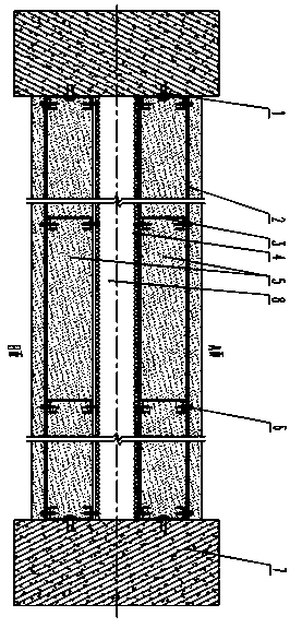
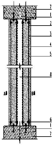
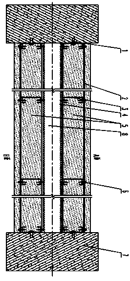
[0004] The object of the present invention is to provide a sound-insulating wall structure to solve the problem of prefabricated materials used in the sound-insulating wall structure proposed in the above-mentioned background technology, especially strip wall, thin-slab composite wall or core board. Most of the walls are made of light materials with low surface density and poor sound insulation, which makes it difficult to meet the minimum sound insulation requirements and bring inconvenience to users; at the same time, in order to solve the environmental pressure brought by industrial solid waste-by-product gypsum problem, looking for a method and way to absorb a large amount of industrial by-product gypsum, for this reason, we propose a sound-insulating wall structure

Method used


Image

  • Sound insulation wall body structure
  • Sound insulation wall body structure
  • Sound insulation wall body structure

Examples


Embodiment Construction

[0024] The following will clearly and completely describe the technical solutions in the embodiments of the present invention with reference to the accompanying drawings in the embodiments of the present invention. Obviously, the described embodiments are only some, not all, embodiments of the present invention. Based on the embodiments of the present invention, all other embodiments obtained by persons of ordinary skill in the art without making creative efforts belong to the protection scope of the present invention.

[0025] In the description of the present invention, unless otherwise stated, the meaning of "plurality" is two or more; the terms "upper", "lower", "left", "right", "inner", "outer" , "front end", "rear end", "head", "tail", etc. indicate the orientation or positional relationship based on the orientation or positional relationship shown in the drawings, and are only for the convenience of describing the present invention and simplifying the description, rather...


PUM


Abstract

The invention relates to a sound insulation wall body structure. The sound insulation wall body structure includes an A face spraying constructing composite wall body and a B face spraying constructing composite wall body and an air layer enclosing the A face spraying constructing composite wall body and the B face spraying constructing composite wall body, wherein the A face spraying constructingcomposite wall body and the B face spraying constructing composite wall body are independent, and the air layer is arranged in the middle of the sound insulation wall body structure; and materials such as a light steel keel skeleton, a steel wire net, wall body spraying constructing mortar are assembled in site to form the spraying constructing wall body in a continuous spraying constructing mode. The sound insulation wall body structure has the beneficial effects that a solid-air-solid double-layer structure is formed by the two independent separated spraying constructing composite wall bodies and the enclosed air layer, the noise isolation effect is achieved, and the sound bridge phenomenon is avoided; no crack and no hole exist in the spraying constructing composite wall bodies throughthe mode that the wall is formed by continuously spraying constructing, and the phenomena of 'air leakage and noise leakage' are avoided at the maximum extent; and a light steel keel and the steel wire net are adopted to be a skeleton and are an attachment surface and stress supporting of the wall body spraying constructing mortar, the light steel keel and the steel wire net are fixed to buildingstructural components and can be designed according to the height, the length, the thickness and the shape of the wall body, and construction requirements of any wall surface are met.

Description

technical field [0001] The invention relates to the technical field of building construction, in particular to a sound insulation wall structure. Background technique [0002] At present, noise has become a major environmental pollution, and the acoustic environment of buildings has been paid more and more attention to. It is the most important thing in building noise control engineering to select appropriate materials for sound absorption and sound insulation of buildings. One of the most basic technical measures commonly used, the frequency of noise in modern society is getting higher and higher, so the effect of sound insulation on walls is also higher. The prefabricated materials used in the construction of sound-insulating walls on the market, especially slat walls, thin-board composite walls or core-board walls, are mostly light-weight materials with low surface density and poor sound insulation, which makes it difficult to meet the minimum requirements. The requireme...

Claims


Application Information

Patent Timeline
Patent Type & Authority Applications(China)
IPC IPC(8): E04B2/76E04B1/82E04B1/94E04B2/82E04B1/98E04H9/02
CPCE04B2/76E04B1/82E04B1/94E04B2/82E04H9/021
Inventor 谢日清陈榕基
Owner SHANGHAI KENAI NEW MATERIAL TECH CO LTD
Learn More