Gas-liquid separator

A technology of gas-liquid separator and separation chamber, which is applied in refrigeration and liquefaction, compressors, refrigeration components, etc., and can solve the problems of the third gas-liquid separator, such as the need to improve efficiency, compactness and low space utilization, and ejector Entrainment effect is not strong and other problems, to achieve the effect of improving gas kinetic energy and ejection efficiency, improving space utilization, and compact structure

Pending Publication Date: 2019-07-05
NORTHWESTERN POLYTECHNICAL UNIV
View PDF6 Cites 5 Cited by
  • Summary
  • Abstract
  • Description
  • Claims
  • Application Information

AI Technical Summary

Problems solved by technology

To sum up, in view of the current development status of ejector refrigeration, there are still three technical problems to be solved. The first is to strengthen the entrainment effect of the ejector and the efficiency of the ejector is not high. The second is to design the system The compactness of the space utilization rate is not high, and the matching problem between the ejector and the gas-liquid separator in the design also needs to be solved, and the efficiency of the third gas-liquid separator needs to be improved

Method used


Image

  • Gas-liquid separator
  • Gas-liquid separator
  • Gas-liquid separator

Examples


Embodiment Construction

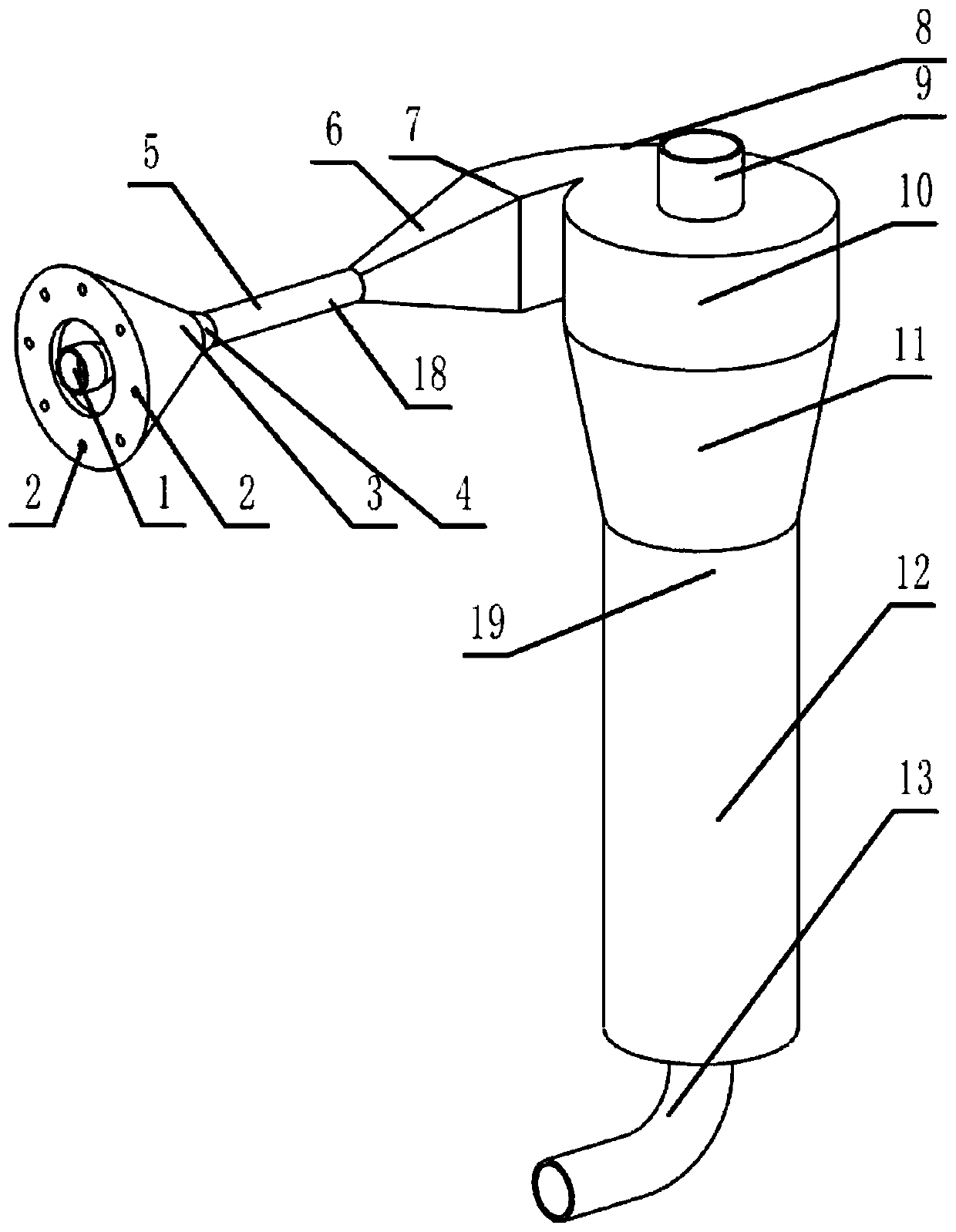
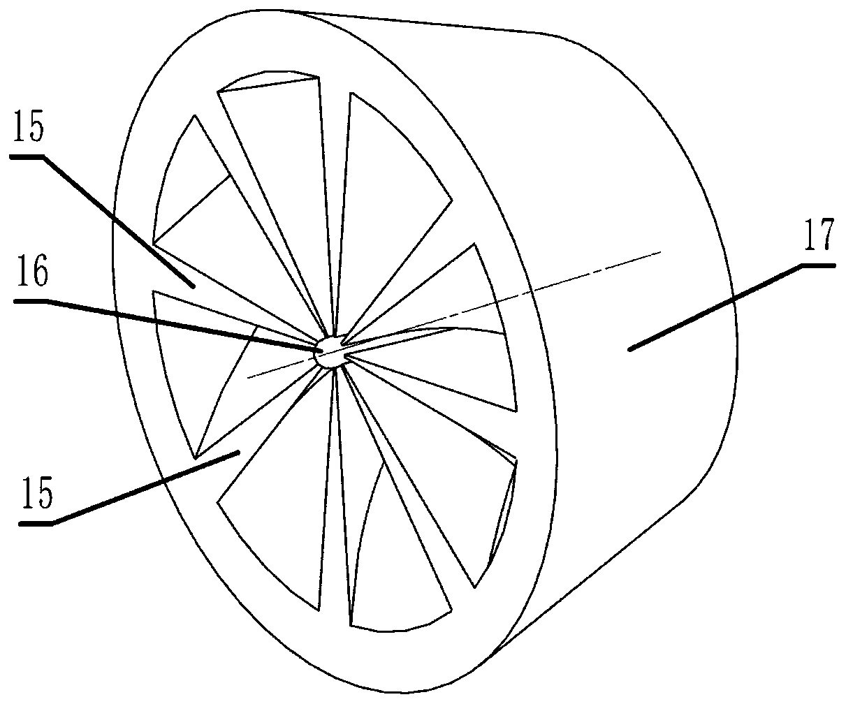
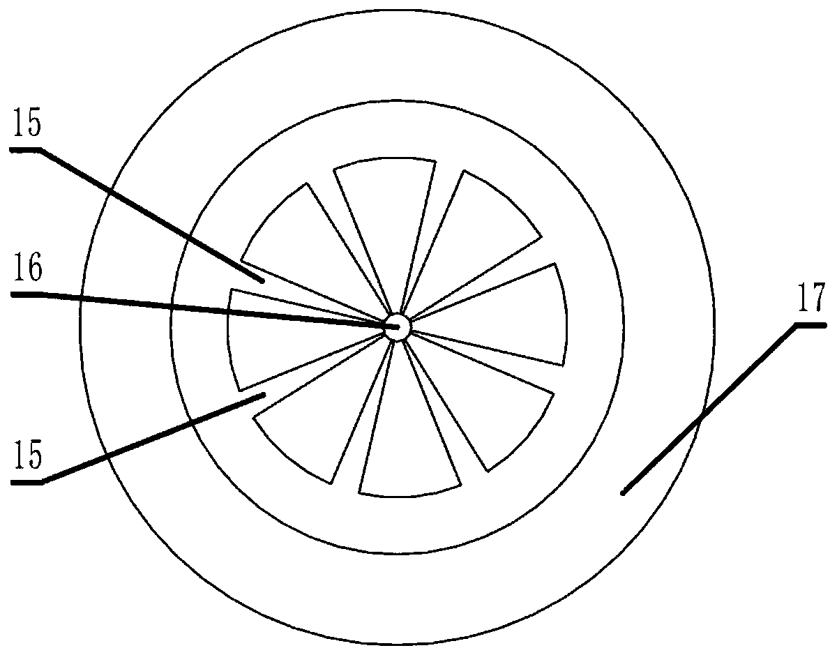
[0024] For the above-mentioned problems to be solved, such as figure 1 As shown, in order to improve the compactness of the system design and the space utilization rate, the present invention combines the injection function with the gas-liquid separator to carry out an integrated design, that is, eight injection holes 2, injection nozzles 14, injection Chamber 3, swirl generator 4, mixing section 5, and diffuser section 6 integrally form the inlet 18 of the gas-liquid separator, the junction of diffuser section 6 and mixing section 5 is circular, and the junction of the other end and pre-swirling section 8 is Rectangular, the design of the pre-swirl section inlet 7 is rectangular to reduce the pressure loss entering the pre-swirl section 8, the gas-liquid mixture obtains a circumferential velocity when flowing through the pre-swirl section 8, and the centrifugal force generated makes the liquid with a large difference in density Separated from the gas, the centrifugal dynamic ...


PUM


Abstract

The invention discloses a gas-liquid separator. The gas-liquid separator comprises a tank, wherein a gas-liquid separator inlet flow passage is arranged on the tank and is sequentially connected to apre-rotation section and a pre-rotation cavity; the middle part of the tank is a separation cavity; the lower part of the tank is a liquid storage cavity; a liquid discharging pipe located at the bottom communicates with the liquid storage cavity; a gas discharging pipe goes deep into the central position of the tank; the gas-liquid separator inlet flow passage is an injecting device with a swirling function; when a liquid working medium flows through an injecting nozzle, a gas working medium of an injecting hole is sucked, the liquid working medium and the gas working medium are mixed by a swirling generator and are pressurized at a diffusion section, and then the mixture is separated into liquid and gas under the action of centrifugal force; the liquid is discharged by the liquid discharging pipe in the liquid storage cavity, and enters an expansion valve; and the gas is discharged by the gas discharging pipe, and enters a compressor, thus, the primary injection and the gas-liquid separation are completed. The gas-liquid separator can improve the injection efficiency of a jet type refrigeration system, then improves the refrigeration efficiency, meanwhile increases the utilization rate of space of the system, enhances the compactness of the system, and has relatively high gas-liquid separation efficiency.

Description

technical field [0001] The invention belongs to the technical field of jet refrigeration, in particular to a gas-liquid separator. Background technique [0002] The ejector refrigeration system usually designs an ejector and a gas-liquid separator. The high-temperature and high-pressure gas refrigerant after being boosted by the compressor enters the condenser to condense and dissipate heat, and then accelerates and depressurizes in the ejector. The pressure difference between the outlet of the evaporator and the high-temperature refrigerant at the outlet of the evaporator pumps this part of the gaseous refrigerant, and enters the gas-liquid separator after mixing. The separated liquid refrigerant enters the expansion valve and the evaporator in turn for heat exchange, and the gaseous refrigerant Going back to the compressor to boost the pressure, the purpose of this design is to use the ejector to increase the pressure of the low-pressure gaseous refrigerant at the outlet o...

Claims


Application Information

Patent Timeline
Patent Type & Authority Applications(China)
IPC IPC(8): F25B43/00F25B9/08
CPCF25B43/00F25B9/08
Inventor 田强刘振侠胡剑平
Owner NORTHWESTERN POLYTECHNICAL UNIV
Why Eureka
Try Eureka