Drying method and energy-saving drying equipment

A technology of drying equipment and drying area, which is applied in the direction of drying, drying machine, lighting and heating equipment, etc., can solve the problems of high energy consumption, long time consumption, moisture return, etc., and achieve high energy efficiency and wide range of energy utilization Effect

Pending Publication Date: 2019-07-05
苏州达善净化科技有限公司
View PDF4 Cites 1 Cited by
  • Summary
  • Abstract
  • Description
  • Claims
  • Application Information

AI Technical Summary

Problems solved by technology

However, this drying method not only takes a long time and consumes a lot of energy, but also the dried items still contain a certain amount of water, which leads to the fact that when the items are taken out from the drying area and placed in a normal temperature environment after drying, the temperature of the items drops. There will be a phenomenon of "resurgence"

Method used


Image

  • Drying method and energy-saving drying equipment
  • Drying method and energy-saving drying equipment
  • Drying method and energy-saving drying equipment

Examples


Embodiment 1

[0039] Embodiment 1 drying method

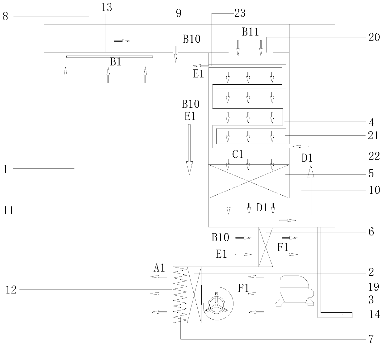
[0040] like Figure 1-2 As shown, a drying method in this embodiment is to use heating gas to dry items, and the drying method specifically includes:

[0041] (1) Put the article in the preset drying zone 1 , the drying zone 1 has a heating gas inlet 12 and a heating gas outlet 13 .

[0042] (2) The heating gas is passed into the drying zone 1 from the heating gas inlet 12, and after the articles in the drying zone 1 are heated, the drying zone 1 is discharged from the heating gas outlet 13, wherein the discharged from the drying zone 1 The heating gas is divided into two streams.

[0043] (3) After dehumidifying and heating one of the two heated gases in sequence, it is re-introduced into the drying area; the dehumidification is realized by cooling the heated gas. The gas to be dehumidified accounts for 20%-98% of the total volume of the gas output from the drying zone, preferably 30%-50%, more preferably 30%.

[0044] A heat recovery d...

Embodiment 2

[0059] Embodiment 2 Energy-saving drying equipment

[0060] like Figure 1-2 As shown, a kind of energy-saving drying equipment in this embodiment includes a drying chamber, a heating device 2 for heating the gas to form heated gas, an air supply device 3 for delivering heated gas to the drying chamber, and exhausting the heated gas to the drying chamber. The heat recovery device 4 for heat recovery of the gas, the first return air duct 9 connecting the drying chamber and the heat recovery device 4, the cooling device 5 for condensing and dehumidifying the gas, and the gas output from the cooling device 5 to be transported to The second return air duct 10 of the heat recovery device 4 is used to deliver the gas output from the heat recovery device 4 or the gas output from the first return air duct 9 to the third return air duct 11 of the air supply device 3 . A drying zone 1 is preset in the drying chamber.

[0061] The heat recovery device 4 includes a first heat exchange c...

Embodiment 3

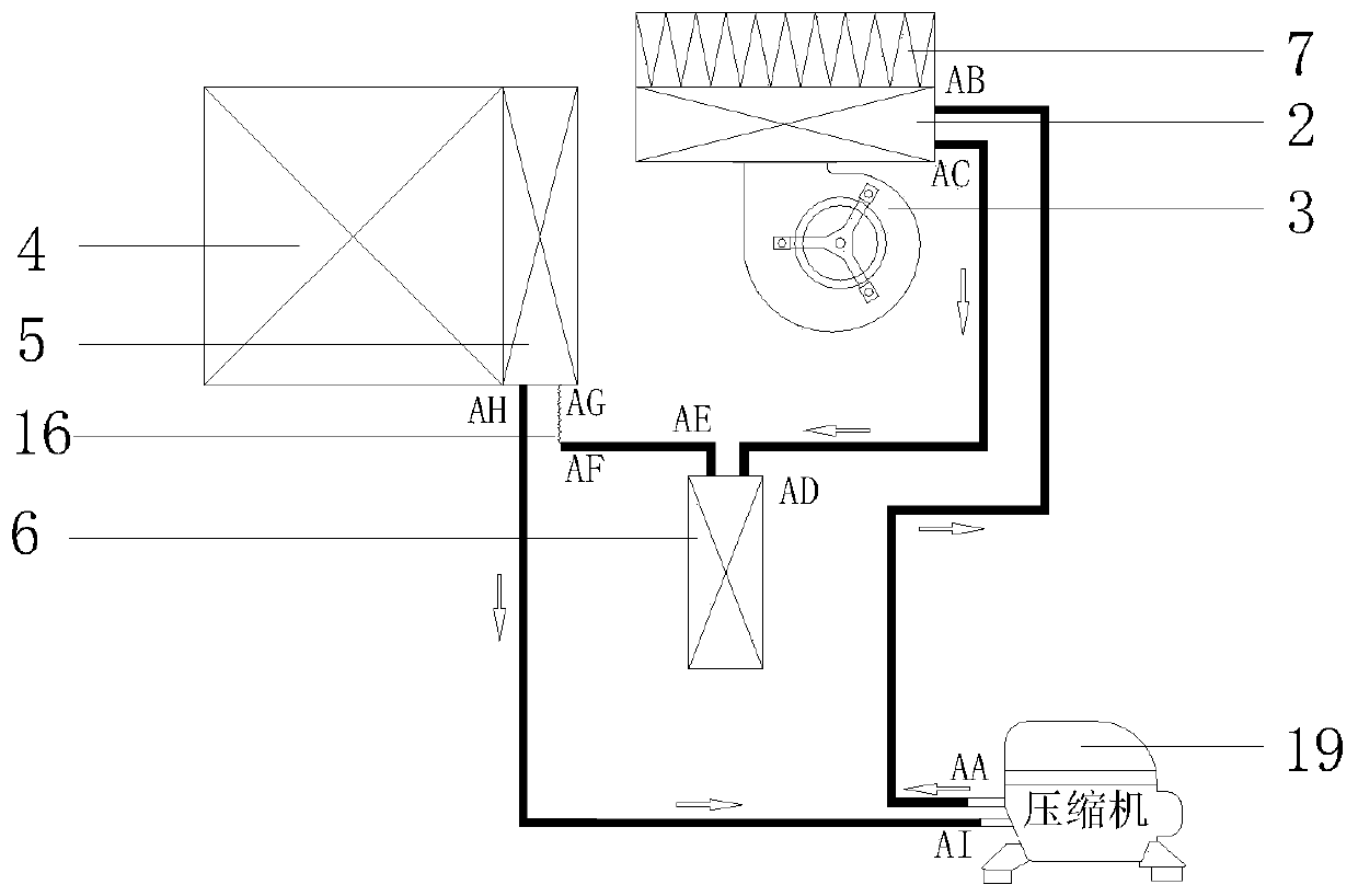
[0080] Example 3 Working trend of refrigerant in energy-saving drying equipment

[0081] like figure 2 As shown, the working direction of the refrigerant in the energy-saving drying equipment in Example 2 is as follows, where the arrow represents the direction of the refrigerant:

[0082] (1) Compressor 19 is set, and when compressor 19 is running, the internal refrigerant is compressed to form a high-temperature and high-pressure refrigerant that is discharged from the exhaust port of compressor 19, and the high-temperature and high-pressure refrigerant enters heating device 2 through copper pipes;

[0083] (2) The high-temperature and high-pressure refrigerant exchanges heat with the gas F1 in the heating device 2, heats the gas F1 into gas A1, and the gas A1 enters the drying zone 1, and the refrigerant formed at room temperature and high pressure is discharged from the outlet of the heating device 2 , enter the reheating mechanism 6 through the copper tube.

[0084] (3)...


PUM


Abstract

The invention discloses a drying method. Heating gas is utilized for drying objects. The drying method specifically comprises the following steps that firstly, the objects are placed in the preset drying area, and the drying area is provided with a heating gas inlet and a heating gas outlet; secondly, the heating gas is led into the drying area from the heating gas inlet, and after the objects inthe drying area are heated, the heating gas is discharged out of the drying area from the heating gas outlet, and the heating gas discharged out of the drying area is divided into two paths; thirdly,after one of the two paths of the heating gas is sequentially dehumidified and heated, the heating gas is led into the drying area again; and fourthly, the other one of the two paths of the heating gas is heated and then is led into the drying area again. According to the low-humidity drying method, energy saving is obvious, water in the gas in the drying area is removed two times, and it is guaranteed that the water removal phenomenon is generated to the objects needing to be dried in the drying area in the low-humidity environment.

Description

technical field [0001] The invention belongs to the technical field of drying equipment and drying methods, and in particular relates to a drying method and energy-saving drying equipment based on the drying method. Background technique [0002] The existing drying equipment on the market generally uses electric heating directly for heating and drying, or uses a heat pump unit to use the compressor to compress the refrigerant to generate heat, and the heat emitted by the condenser after heat exchange is used for drying. The temperature in the drying area rises to achieve the purpose of drying the articles in the drying area. However, after the air in the drying area is heated, the moisture content of the air increases greatly. Although the humid air in the drying area will be exhausted through sensors or timing settings, and then the outside air will be sucked in for drying and wetting. air exchange. However, this drying method not only takes a long time, but also consumes...

Claims


Application Information

Patent Timeline
IPC IPC(8): F26B9/06F26B21/02F26B25/22
CPCF26B9/06F26B21/002F26B21/02F26B25/22Y02P70/10
Inventor 沈文荣
Owner 苏州达善净化科技有限公司
Why Eureka
Try Eureka