Pressurized water experiment equipment and method based on coal body or rock-body loose circle detection

A technology of pressurized water experiment and loose ring, which is used in measuring devices, using stable tension/pressure to test material strength, suspension and porous material analysis, etc. The problem of breaking the gas supply pipeline, etc., can improve the observation efficiency, adjust the pressure sensitivity and balance, and shorten the detection time.

Pending Publication Date: 2019-07-05
SHANDONG UNIV OF SCI & TECH
View PDF12 Cites 3 Cited by
  • Summary
  • Abstract
  • Description
  • Claims
  • Application Information

AI Technical Summary

Problems solved by technology

In the traditional device, there are two external systems, the water injection operation platform and the plugging operation platform. There are relatively many operators, and there are 2 pipes corresponding to the drilled holes. During the propelling process, mutual entanglement is prone to occur, and at least it will cause the device to be blocked. If it is blocked or the observation process is unstable, it is easy to break the gas supply pipeline, causing the equipment to fail to work normally. Moreover, the traditional device is a test unit, and the detection efficiency is low. How to realize multi-segment measurement, reduce the number of pipelines in the borehole, and can Effectively control the water pressure, the existing technology fails to solve the above problems at the same time

Method used


Image

  • Pressurized water experiment equipment and method based on coal body or rock-body loose circle detection
  • Pressurized water experiment equipment and method based on coal body or rock-body loose circle detection
  • Pressurized water experiment equipment and method based on coal body or rock-body loose circle detection

Examples


Embodiment Construction

[0047] The present invention will be described in further detail below in conjunction with specific embodiments.

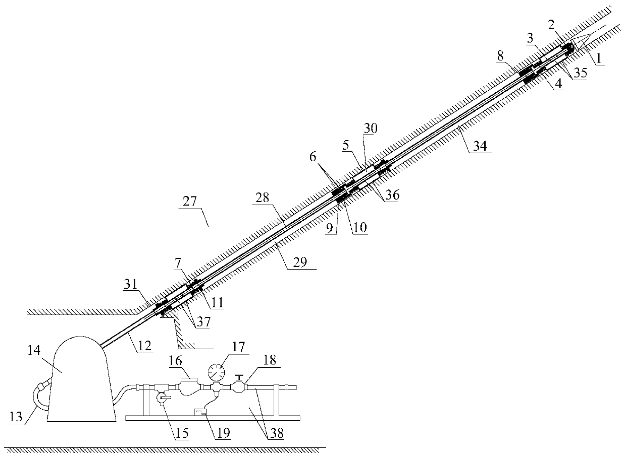
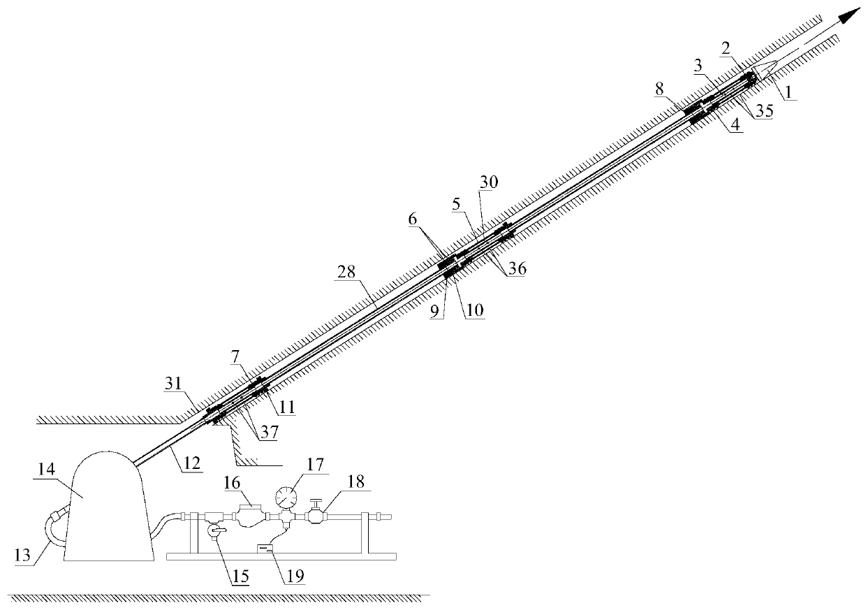
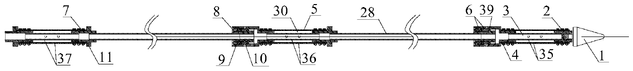
[0048] With reference to the accompanying drawings, the pressurized water test equipment based on coal or rock loose circle detection mainly includes a test probe, a control console 38 , a drilling rig 14 and a drill pipe 12 . The test probe comprises a front occluder 35, a middle occluder 36, a tail occluder 37, a converter 6, a connecting pipe 28, etc., and the front occluder, the middle occluder and the tail occluder Each includes a leaking pipe 3, joints connected to both ends of the leaking pipe 3, and a rubber bag 5. The rubber bag 5 is wrapped around the periphery of the leaking pipe 3, and forms a blocking cavity 30 with the leaking pipe 3, and the external water source is injected into the The plugging cavity 30 swells the rubber bag 5 and forms a water injection cavity with the borehole 31. The drilling rig 14 is connected with the test probe through th...


PUM

PropertyMeasurementUnit
diameteraaaaaaaaaa
lengthaaaaaaaaaa

Abstract

The invention discloses pressurized water experiment equipment based on coal body or rock-body loose circle detection. The equipment comprises a test probe, a drilling machine, a drilling rod and a control operation bench. The test probe comprises a connection pipe. The connection pipe is arranged along a drill hole. A front portion, a middle portion and a tail portion of the connection pipe are provided with a front portion plugging device, a middle portion plugging device and a tail portion plugging device. When a plugging cavity is filled with water, the front portion plugging device, the middle portion plugging device and the tail portion plugging device separate the drill hole so as to form a number one water injection cavity and a number two water injection cavity. The drilling machine is connected to the test probe through the drilling rod so as to lengthen and advance the test probe to a designated area. The control operation bench comprises a high pressure flexible pipe. The control operation bench is connected to the drilling machine through the high pressure flexible pipe. In the invention, integration of plugging and testing of the test probe is realized, the number ofpipelines which work simultaneously in the drill hole is reduced, a problem of mutual intertwining of multiple pipelines in the drill hole during an advancement process is solved, and stability of a measurement process of a rock mass damage range is improved.

Description

technical field [0001] The invention belongs to the technical field of rock mass damage range measurement, and in particular relates to a pressurized water test equipment and method based on coal mass or rock mass loose circle detection. Background technique [0002] The measurement of the range and permeability of the rock mass mining fracture zone is the basic parameter for studying the failure characteristics of the rock mass. It is of great significance for further exploring the relationship between it and the movement law and stress field of the rock mass. Variable electromagnetic method, microseismic detection and pressure water test method. [0003] Among them, the pressure water test method is the most reliable. The traditional device "double-ended side leakage device" is used to conduct water injection and discharge tests to determine the development height or depth of the rock formation affected by mining. In the traditional device, there are two external systems,...

Claims


Application Information

Patent Timeline
Patent Type & Authority Applications(China)
IPC IPC(8): G01N3/12G01N15/08
CPCG01N3/12G01N15/0806G01N15/0826G01N2203/0019G01N2203/0048G01N2203/0062
Inventor 赵春波宋文成
Owner SHANDONG UNIV OF SCI & TECH
Why Eureka
Try Eureka