Method for generating rotatable optical focal field on basis of radiation field of rotating field antenna

A technology of rotating field and radiation field, applied in the field of optics

Active Publication Date: 2019-07-05
QUANZHOU NORMAL UNIV
View PDF4 Cites 11 Cited by
  • Summary
  • Abstract
  • Description
  • Claims
  • Application Information

AI Technical Summary

Problems solved by technology

However, the intensity distribution of the optical focal field in the above-mentioned

Method used


Image

  • Method for generating rotatable optical focal field on basis of radiation field of rotating field antenna
  • Method for generating rotatable optical focal field on basis of radiation field of rotating field antenna
  • Method for generating rotatable optical focal field on basis of radiation field of rotating field antenna

Examples


Embodiment Construction

[0036] In order to make the features and advantages of this patent more obvious and easy to understand, the following special examples are described in detail as follows:

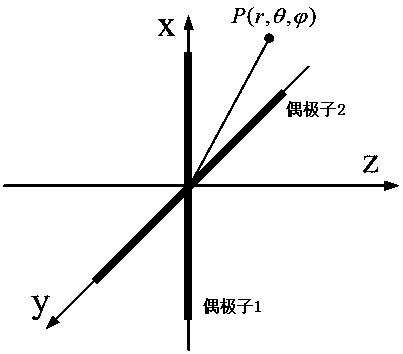
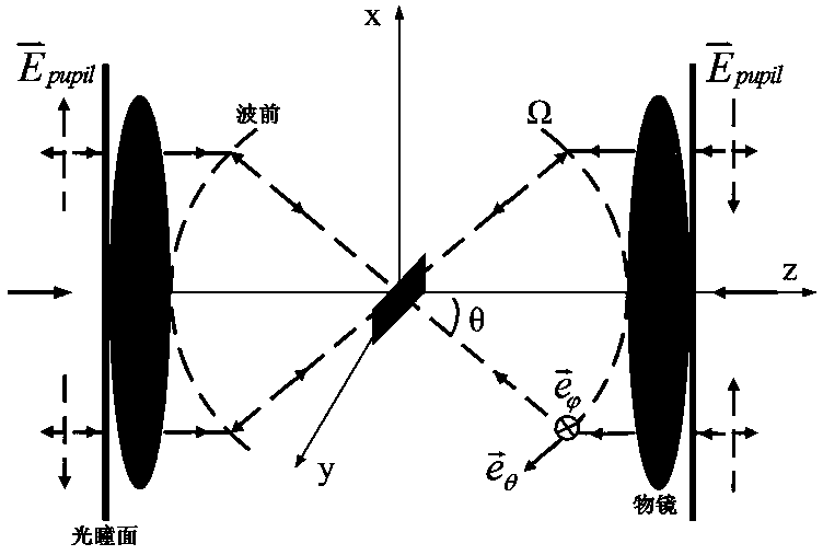
[0037] In this embodiment, the schematic diagram of generating the rotating optical focal field is shown as figure 1 , figure 2 As shown, in this embodiment, the required incident field can be obtained by means of the radiation field of the virtual rotating field antenna. The virtual rotating field antenna is composed of two coplanar dipoles that are perpendicular to each other and fed orthogonally. It can be used as a broadcasting transceiver antenna in the VHF and UHF bands, producing a horizontally polarized omnidirectional radiation pattern.

[0038] exist figure 1 Among them, a schematic diagram of a virtual rotating field antenna composed of two mutually perpendicular dipoles with a phase difference of 90° is given.

[0039] figure 2 It is then based on a 4π focusing system, where a virtual rot...


PUM


Abstract

The invention provides a method for generating a rotatable optical focal field on the basis of a radiation field of a rotating field antenna. The method is characterized by comprising the following steps: S1, placing a virtual rotating field antenna composed of two dipoles which are perpendicular to each other and have a phase difference of 90 degrees at the center of a focal plane of a 4Pi focusing system, so that an electromagnetic field radiated by the virtual rotating field antenna is completely converged by two opposite high numerical aperture lenses and collimated onto a pupil plane; andS2, focusing two incident fields different for 180 degrees onto the optical focal plane of the two opposite high numerical aperture lenses by virtue of the two opposite high numerical aperture lenses. Intensity distribution of an '8'-shaped optical focal field generated by the method provided by the invention rotates at a circular frequency omega around an optical axis on the focal plane along with time. The rotatable optical focal field has important application value in the aspects of particle rotation, particle acceleration and near-field scanning optical microscopes.

Description

technical field [0001] The invention belongs to the field of optics, in particular to a method for generating a rotatable optical focal field based on a radiation field of a rotating field antenna. Background technique [0002] At present, the unique focal field generated by the tight focusing of the vector light field has attracted extensive attention because of its promising application prospects in many aspects such as optical capture and control, optical microscopy, and optical micromachining. [0003] A variety of unique optical focal field distributions, such as light needle, spherical spot, light pipe, light chain, light bubble, flat-top focus, etc., have been reported both theoretically and experimentally. However, the intensity distribution of the optical focal field in the above existing implementation methods is static and remains unchanged near the focal point. Contents of the invention [0004] Aiming at the deficiencies and gaps in the prior art, based on th...

Claims


Application Information

Patent Timeline
IPC IPC(8): G02F1/29
CPCG02F1/29G02F1/292G02F1/294
Inventor 余燕忠林雪华
Owner QUANZHOU NORMAL UNIV
Why Eureka
Try Eureka