Image scanning pathological section system

A pathological section and image scanning technology, applied in the field of image scanning pathological section systems, can solve the problems of difficult real-time diagnosis, inaccurate diagnosis results, and ineffective diagnosis results in system diagnosis, and achieve strong real-time diagnosis, good diagnosis effect, The effect of high diagnostic intelligence

Pending Publication Date: 2019-07-05
北京金智拓科技有限公司
View PDF7 Cites 2 Cited by
  • Summary
  • Abstract
  • Description
  • Claims
  • Application Information

AI Technical Summary

Problems solved by technology

[0005] The above-mentioned patent documents disclose a digital pathology remote diagnosis system and method based on digital slices, but it is difficult to achieve real-time diagnosis, the diagnosis result is not accurate, and the diagnosis effect cannot satisfy the majority of patients.

Method used


Image

  • Image scanning pathological section system
  • Image scanning pathological section system

Examples


Embodiment 1

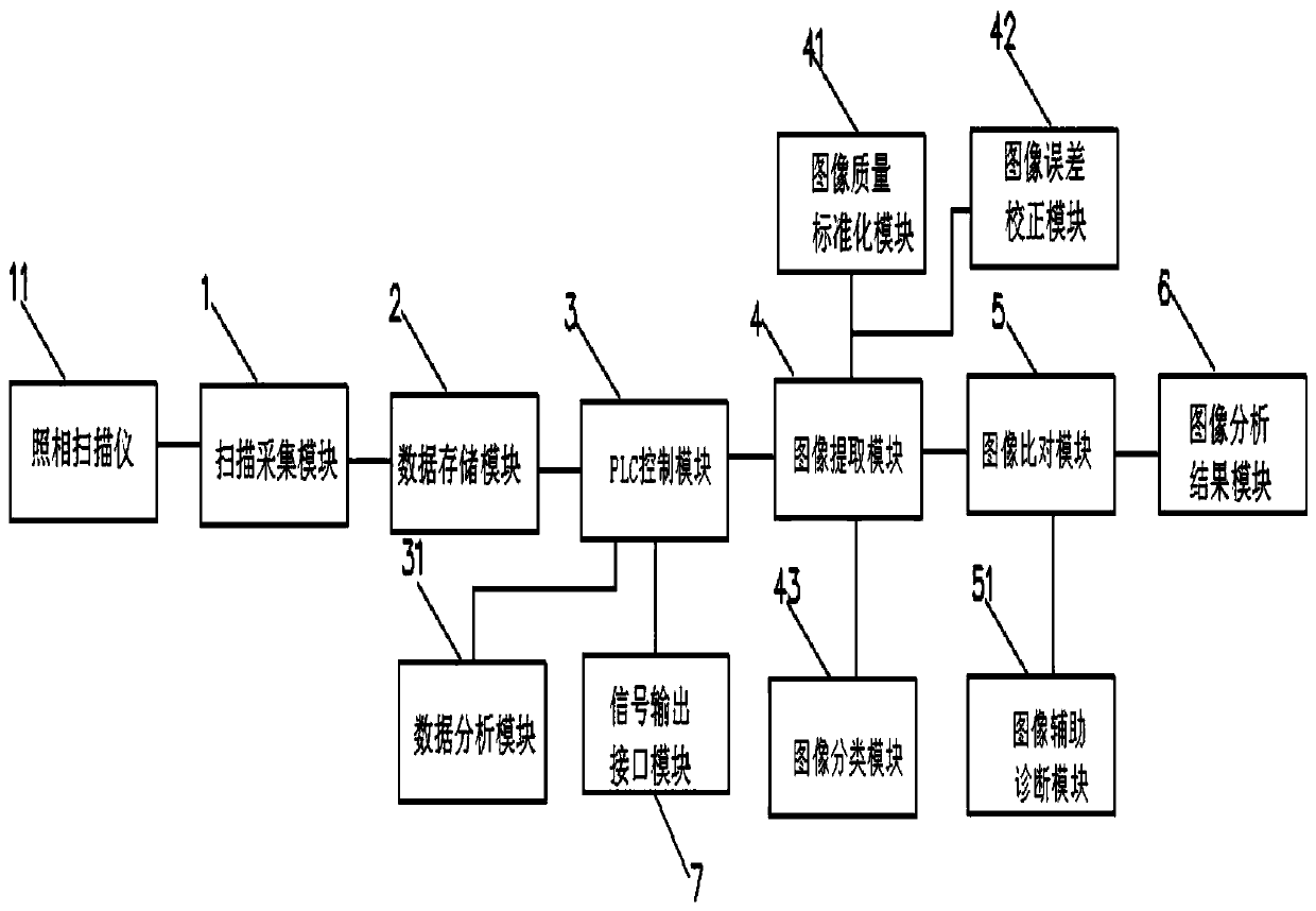
[0021] see figure 1 , an image scanning pathological slicing system, comprising a scanning acquisition module 1, a data storage module 2, a PLC control module 3, an image extraction module 4, an image comparison module 5, an image analysis result module 6, and a signal output interface module 7; The scan collection module 1 is used to collect image data of scanned pathological slices; the data storage module 2 is used to save image data; the PLC control module 3 is used to control and process image data; the image extraction module 4 is used to Extracting the feature points of pathological slice images; the image comparison module 5 is used for comparing and analyzing the extracted feature point pathological slice images with the stored pathological slice images; the image analysis result module 6 is used for comparing the images Judgment processing; the signal output interface module 7 is used to control signal output;

[0022] Described scanning acquisition module 1 transmi...

Embodiment 2

[0028] see figure 1 , the difference from the above embodiment is that the image extraction module 4 of the present invention includes an image quality standardization module 41, which is used to standardize the image quality.

[0029] The image extraction module 4 includes an image error correction module 42, which is used to correct image errors.

[0030] The image extraction module 4 includes an image classification module 43, which is used for automatic classification and quantitative index analysis and judgment on the extracted images.

[0031] In this embodiment, the image extraction module 4 includes an image quality standardization module 41 to further standardize the pathological slice images, including standardizing the color, definition and size of the pictures, so as to make the analysis of pathological results more accurate and effective.

[0032] The image error correction module 42 corrects the pathological slice image errors to ensure more accurate diagnosis r...


PUM


Abstract

The invention discloses an image scanning pathological section system which comprises a scanning acquisition module, a data storage module, a PLC control module, an image extracting module, an image contrasting module, an image analysis result module and a signal output interface module. The scanning acquisition module transmits the acquired image information to the PLC control module through thedata storage module. The PLC control module transmits a control signal to the image contrasting module through the image extracting module. The image contrasting module transmits contrasting information to the image analysis result module. The PLC control module controls signal outputting of the signal output interface module. The image scanning pathological section system according to the invention has advantages of high real-time performance, accurate diagnosis result and high diagnosis effect.

Description

technical field [0001] The invention relates to the technical field of medical image processing, in particular to an image scanning pathological slicing system. Background technique [0002] At present, clinical pathological diagnosis is the most intuitive and accurate gold standard for disease diagnosis. Through the observation of diseased tissue under a microscope, the cancer can be diagnosed and the malignancy of the cancer can be obtained through analysis. Post is expected to provide the best approach. With the rapid development of computer and information technology, high-resolution panoramic imaging of pathological slices has been realized, and digital pathological slice data have been obtained. Pathological image diagnosis still relies on manual image reading. On the one hand, the work is heavy and the professional requirements are high; on the other hand, it is easily limited by the subjectivity of doctors’ experience. The sample size has increased greatly, and the...

Claims


Application Information

Patent Timeline
Patent Type & Authority Applications(China)
IPC IPC(8): G16H50/20G06T7/00
CPCG16H50/20G06T7/0012G06T2207/30024
Inventor 鞠宪贵
Owner 北京金智拓科技有限公司
Why Eureka
Try Eureka