Synchronous rectification control circuit and control method thereof

A technology of synchronous rectification and control method, which is applied in the direction of control/regulation system, electrical components, and regulation of electric variables, etc., which can solve the problems of inaccurate sampling of auxiliary winding voltage, loss of control of the loop, and wrong judgment, etc., to achieve improved synchronous rectification Efficiency, increased reliability, reduced time effects

Active Publication Date: 2019-07-05
SHENZHEN NANYUN MICROELECTRONICS CO LTD
View PDF6 Cites 19 Cited by
  • Summary
  • Abstract
  • Description
  • Claims
  • Application Information

AI Technical Summary

Problems solved by technology

However, there are inherent defects in the primary side feedback: ① affected by the voltage drop of the rectifier device, the voltage on the auxiliary winding is not the real output voltage of the converter; ② affected by the turn ratio of the auxiliary winding and the secondary winding, This turn ratio varies to a certain extent with the production process; ③ affected by the sampling circuit of the primary side, the primary side controller cannot accurately sample the voltage of the auxiliary winding
Since the entire control scheme proposed in the above patent literature will cause a certain low-frequency ripple in the output voltage of the converter, when the output voltage change of two adjacent cycles reaches the set threshold, it will cause a wrong judgment on the primary side, making the loop road out of control
In order to improve the reliability of the primary side detection, on the basis of the invention patent application CN105610306A, a Chinese invention patent application with the publication number CN107612334A has been produced, which detects the voltage FA after the auxiliary winding is divided in the same cycle during the degaussing time Whether there is a voltage rising slope in the segment to judge whether the output voltage is high or low, such as figure 2 As shown, due to the limitations in the specific implementation of the scheme, a Chinese invention patent with the application publication number CN109298224A was proposed. The specific limitations of the Chinese invention patent with the publication number CN107612334A can refer to the background of the Chinese invention patent with the application publication number CN109298224A As described in the technology, in the Chinese invention patent with the application publication number CN109298224A, three signals of a rising slope, a falling slope and the duration between the rising slope and the falling slope of the FA voltage VA after the auxiliary winding are divided are used to jointly judge whether a Effective output voltage high signal, this primary side signal detection method can realize this kind of secondary side control scheme, but there is a disadvantage, synchronous rectification is used to reduce the loss of secondary side rectification, so synchronous rectification MOS tube selection The smaller the conduction internal resistance, the better. Since the internal turn-off threshold of the chip is fixed, when choosing to use a synchronous rectification MOS transistor with a relatively small internal resistance, no matter whether the output voltage is high or low, the synchronous rectification turn-off point The corresponding current is relatively large, and both ends of the synchronous rectification MOS tube will generate a relatively large slope at the moment of turning off to increase the voltage at both ends. It is judged that the rising slope is valid, and because the current corresponding to the turn-off point is relatively large, the The time to continue degaussing after breaking is relatively long, which is longer than the detection time. After the degaussing ends, a falling slope will be generated, so no matter whether the output is high or low, it will reach the rising slope, falling slope and the holding time between the rising slope and the falling slope. Three conditions, thus causing misjudgment

Method used


Image

  • Synchronous rectification control circuit and control method thereof
  • Synchronous rectification control circuit and control method thereof
  • Synchronous rectification control circuit and control method thereof

Examples


Embodiment Construction

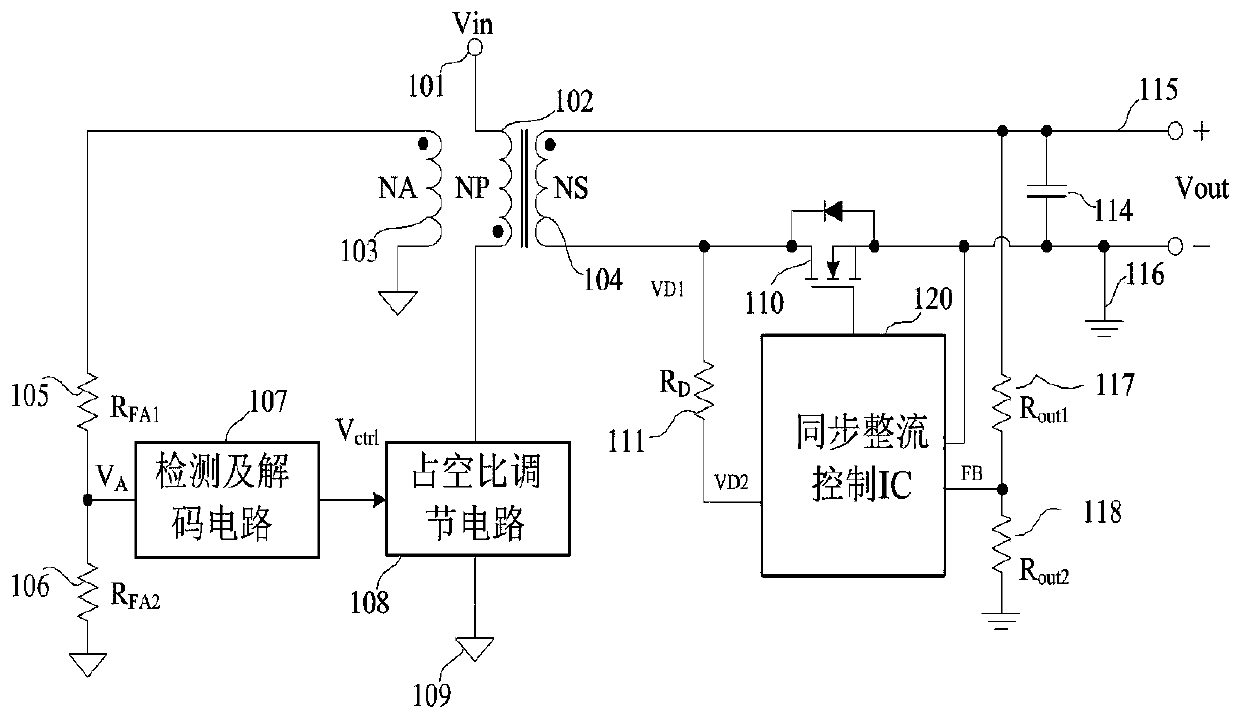
[0032] In order to make the object, technical solution and advantages of the present invention clearer, the following in conjunction with the attached Figure 5 , with Figure 6 , with Figure 7 , with Figure 8 , with Figure 9 , with Figure 10 The important links in the present invention are further described in detail. The synchronous rectification control circuit 120 includes a detection and encoding circuit 112, and a synchronous rectification drive circuit 113, wherein the detection and encoding circuit includes a threshold detection circuit, a threshold generation circuit, an output voltage detection circuit, and a logic control circuit. The synchronous rectification drive circuit includes a soft-off circuit, Signal amplification circuit. The threshold detection circuit samples the voltage at both ends of the drain and source of the synchronous rectification MOS transistor and compares it with the internally set threshold, then outputs a corresponding control sign...


PUM


Abstract

The invention provides a synchronous rectification control circuit and a control method thereof. The synchronous rectification control circuit comprises a threshold detection circuit, a threshold generation circuit, an output voltage detection circuit, a logic control circuit, a soft-off circuit and a signal amplification circuit. The threshold detection circuit samples the voltage at the two endsof the drain and the source of the synchronous rectification MOS tube, compares the voltage with an internally set threshold and outputs a corresponding control signal to the logic control circuit; the output voltage detection circuit detects the output voltage, judges whether the output voltage exceeds a preset reference voltage or not, and outputs a signal to the logic control circuit; the logic control circuit processes signals output by the threshold detection circuit and the output voltage detection circuit and outputs a control signal to the signal amplification circuit, and the signalamplification circuit amplifies the control signal and then outputs a synchronous rectification driving signal; and a soft turn-off circuit realizes a soft turn-off function. The synchronous rectification control circuit can enable the primary side detection circuit to be judged easily, and improves the reliability; and the time of secondary side current passing through the body diode is reduced through soft turn-off, and the synchronous rectification efficiency is improved.

Description

technical field [0001] The invention relates to a synchronous rectification control circuit and a control method thereof, in particular to a synchronous rectification control circuit and a control method thereof applied in secondary side feedback control. Background technique [0002] In the primary-side control scheme of the flyback isolated converter, the output voltage or current information needs to be fed back to the primary-side controller to realize closed-loop control. Commonly used feedback techniques are secondary side feedback and primary side feedback. Among them, the task of secondary side feedback is completed by the isolation amplifier composed of device TL431, optocoupler and auxiliary devices. The output voltage of the converter and the reference voltage are compared and amplified by TL431 to give an error signal. The error signal flows through the input terminal of the optocoupler in the form of current, and the output terminal of the optocoupler draws cur...

Claims


Application Information

Patent Timeline
Patent Type & Authority Applications(China)
IPC IPC(8): H02M3/335
CPCH02M3/33592H02M1/0058Y02B70/10
Inventor 赵永宁肖华汪志远
Owner SHENZHEN NANYUN MICROELECTRONICS CO LTD
Why Eureka
Try Eureka