Pre-combustion chamber structure of fuel gas engine

A gas engine and pre-combustion chamber technology, which is applied in combustion engines, internal combustion piston engines, machines/engines, etc., can solve the problems of slow combustion speed of the mixture, low power and effective thermal efficiency of the whole machine, and low ignition energy, etc. The effect of high emission, overall power and effective thermal efficiency, and fast combustion speed

Pending Publication Date: 2019-07-09
GUANGXI YUCHAI MASCH CO LTD
View PDF7 Cites 10 Cited by
  • Summary
  • Abstract
  • Description
  • Claims
  • Application Information

AI Technical Summary

Problems solved by technology

[0002] At present, most domestic high-power gas engines adopt the traditional spark plug ignition method, and the ignition energy is low, resulting in the slow burning speed of the mixed gas and the limited concentration of the mixed gas. In the end, the power of the whole machine can only reach 75% to 75% of the prototype diesel engine with the same displacement. 80%, the overall effective thermal efficiency is generally less than 40%, and for high-speed engines or when the combustible gas contains more flame-retardant gases, the overall power and effective thermal efficiency are lower, and the emissions are worse

Method used


Image

  • Pre-combustion chamber structure of fuel gas engine
  • Pre-combustion chamber structure of fuel gas engine

Examples


Embodiment Construction

[0014] The specific embodiments of the present invention will be described in detail below in conjunction with the accompanying drawings, but it should be understood that the protection scope of the present invention is not limited by the specific embodiments.

[0015] Unless expressly stated otherwise, throughout the specification and claims, the term "comprise" or variations thereof such as "includes" or "includes" and the like will be understood to include the stated elements or constituents, and not Other elements or other components are not excluded.

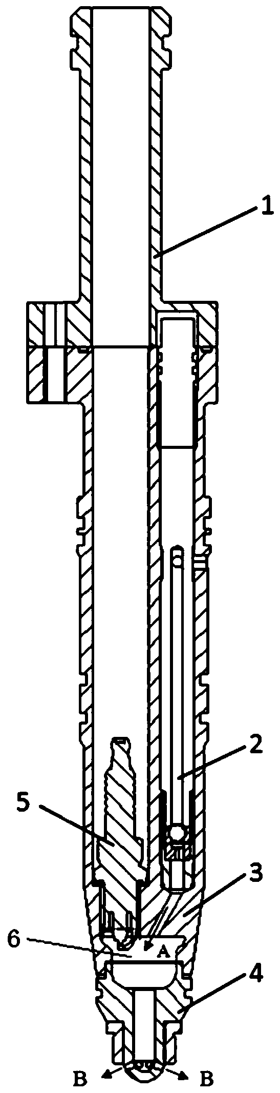
[0016] like figure 1 As shown, the specific structure of the gas engine pre-chamber structure according to the preferred embodiment of the present invention includes: a high-voltage wire bushing 1 , a check valve 2 , a pre-chamber body 3 , a nozzle 4 and a spark plug 5 . Among them, the high-voltage wire sleeve 1 is used to fix the pre-combustion chamber body on the engine cylinder head, and seal the check valve installati...


PUM


Abstract

The invention discloses a pre-combustion chamber structure of a fuel gas engine. The pre-combustion chamber structure of the fuel gas engine comprises a high-voltage guide wire sleeve, a pre-combustion chamber body, a spark plug, a one-way valve and a spray nozzle, wherein the lower end of the pre-combustion chamber body is provided with a pre-combustion chamber upper cavity; a spark plug mountinghole is formed in one side above the pre-combustion chamber upper cavity; a one-way valve mounting hole is formed in the other side above the pre-combustion chamber; the one-way valve mounting hole communicates with the pre-combustion chamber upper cavity through a gas inlet channel; the high-voltage guide wire sleeve is fixedly arranged at the upper end of the pre-combustion chamber body; the upper end of the spray nozzle is provided with a pre-combustion chamber lower cavity; the spray nozzle is arranged at the lower end of the pre-combustion chamber body; the pre-combustion chamber lower cavity and the pre-combustion chamber upper cavity of the pre-combustion chamber body define a pre-combustion chamber cavity; and the lower end of the spray nozzle is provided with a spray channel which communicates with the pre-combustion chamber lower cavity. The pre-combustion chamber structure of the fuel gas engine forms relatively great ignition energy through combustion of a high-concentration natural air mixture to ignite the relatively thin gas mixture in a primary combustion chamber, so that the purpose of improving power and heating efficiency of the whole machine is achieved.

Description

technical field [0001] The invention relates to the field of engines, in particular to a gas engine pre-combustion chamber structure. Background technique [0002] At present, most domestic high-power gas engines adopt the traditional spark plug ignition method, and the ignition energy is low, resulting in the slow burning speed of the mixed gas and the limited concentration of the mixed gas. In the end, the power of the whole machine can only reach 75% to 75% of the prototype diesel engine with the same displacement. 80%, the overall effective thermal efficiency is generally less than 40%, and for high-speed engines or when the combustible gas contains more flame-retardant gases, the overall power and effective thermal efficiency are lower, and the emissions are worse. [0003] The information disclosed in this Background section is only for enhancing the understanding of the general background of the present invention and should not be taken as an acknowledgment or any for...

Claims


Application Information

Patent Timeline
Patent Type & Authority Applications(China)
IPC IPC(8): F02B19/10F02B19/12F02B19/18
CPCF02B19/108F02B19/1023F02B19/12F02B19/18Y02T10/12
Inventor 唐兰谢鹏毛平安曾志龙
Owner GUANGXI YUCHAI MASCH CO LTD
Why Eureka
Try Eureka