
Comprehensive heat management system applied to hypersonic aerocraft or engine

A thermal management system, hypersonic technology, applied in the cooling system of machines/engines, power plants, engine components, etc., can solve problems such as no continuous energy supply, rotating parts not working, heat dissipation, etc.

Pending Publication Date: 2019-07-09
BEIHANG UNIV
View PDF8 Cites 8 Cited by
  • Summary
  • Abstract
  • Description
  • Claims
  • Application Information

AI Technical Summary

Problems solved by technology

At present, a combination of passive thermal protection and active thermal protection is used, and the use of thermal insulation materials and fuel regeneration active cooling system absorbs a large amount of heat load, but the heat is eventually dissipated and not used
[0004] In addition, the normal operation of the on-board electronic equipment in the hypersonic vehicle and the temporary launch operation of the directed energy weapon consume a lot of energy. When the hypersonic aircraft engine is in the ram mode, the rotating parts do not work, and there is no continuous supply of energy. Therefore, the current Some onboard energy systems are difficult to meet the needs of hypersonic vehicles

Method used


Image

  • Comprehensive heat management system applied to hypersonic aerocraft or engine
  • Comprehensive heat management system applied to hypersonic aerocraft or engine

Examples


Embodiment Construction

[0024] In order to make the purpose, technical solutions and advantages of the embodiments of the present invention clearer, the technical solutions in the embodiments of the present invention will be clearly and completely described below in conjunction with the drawings in the embodiments of the present invention. Obviously, the described embodiments It is a part of embodiments of the present invention, but not all embodiments. Based on the embodiments of the present invention, all other embodiments obtained by persons of ordinary skill in the art without making creative efforts belong to the protection scope of the present invention.

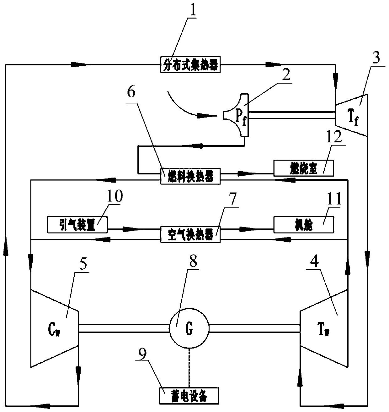
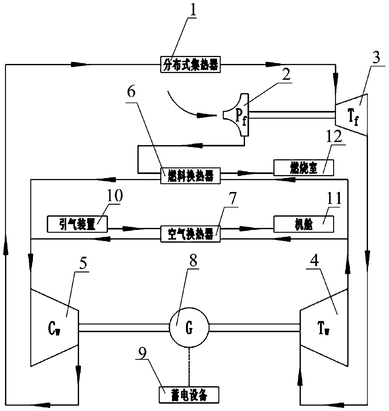
[0025] Please refer to figure 1 , figure 1 It is a schematic layout diagram of an integrated thermal management system for a hypersonic aircraft or engine provided by an embodiment of the present invention.

[0026] The comprehensive thermal management system for a hypersonic aircraft or engine provided by the embodiment of the present inve...


PUM


Abstract

The invention discloses a comprehensive heat management system applied to a hypersonic aerocraft or an engine. The comprehensive heat management system comprises distributed type heat collectors whichare dispersedly distributed on a to-be-cooled high-temperature device positioned on the aerocraft; the outlet of each distributed type heat collector communicates with the inlet of the correspondingdistributed type heat collector through a pipeline to form a closed cycle; each pipeline is provided with a fuel turbine, a working medium turbine and a working medium air compressor; the fuel turbineis used for supplying power to a fuel pump; the working medium turbine is used for supplying power to the working medium air compressor; the working medium air compressor is used for compressing a working medium; and the working medium is a supercritical working medium. By utilizing the characteristics that the supercritical working medium is high in heat exchange capability and small in flow loss, the distributed type heat collectors can be used for collecting lots of heat from the to-be-cooled high-temperature devices such as a strong pre-cooler, a heat protection heat insulating material,avionic electronic equipment, wall surface of a combustion chamber and a lubrication system. The heat can realize additional energy supply. For instance, the fuel turbine and the working medium turbine can do work to output mechanical energy to drive the fuel pump, the working medium air compressor and the like; and meanwhile a generator can also be driven to further transform the energy into electric energy and store the electric energy.

Description

technical field [0001] The invention relates to the technical field of hypersonic aircraft, in particular to an integrated thermal management system for a hypersonic aircraft or engine. Background technique [0002] Hypersonic vehicles have huge military and commercial applications, and world powers are racing to research them. Since hypersonic vehicles put forward extremely high requirements for the power system such as horizontal take-off and landing, repeated use, compact structure, light weight, extremely wide airspace and speed range, a single power cannot meet the demand, and the development of air-breathing combined power is an inevitable trend. [0003] When a hypersonic vehicle flies at a high Mach number, the aerodynamic heating effect is serious, and the outer surface of the vehicle bears a high thermal load. In addition, the onboard electronic equipment, combustion chamber, and lubricating oil system inside the vehicle will also generate large thermal loads. . ...

Claims


Application Information

Patent Timeline
IPC IPC(8): F02C7/22F02C7/224B64D33/10F01D15/08F01D15/10F01K25/10
CPCB64D33/10F01D15/08F01D15/10F01K25/10F01K25/103F02C7/22F02C7/224
Inventor 邹正平王乾王一帆
Owner BEIHANG UNIV
Learn More